FiberQ
FiberQ
FiberQ
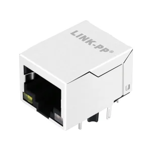
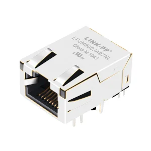
Premium RJ45 interfaces, shielded modular connectors, and active transceivers engineered to support physical link certification testing.
In the modern telecom and enterprise arena, physical layer diagnostics are no longer simple wiremap checks. As data centers migrate from 10G to 400G and 800G optical and copper backplanes, high-precision instrument testing is critical. A single anomalous termination in an RJ45 connector, or microscopic dust on a fiber bulkhead, can result in unacceptable packet loss, high insertion loss, and expensive operational downtime.
Network cable testers act as the first line of defense. By implementing technologies like Time-Domain Reflectometry (TDR), these tools determine cable length, detect resistance anomalies, pinpoint split pairs, and map near-end crosstalk (NEXT). Enterprise network integrators rely on these measurements to certify structured cabling installations to strict standards such as ANSI/TIA-568-D and ISO/IEC 11801.
Without proper verification, PoE (Power over Ethernet) systems risk heat failures, while high-frequency transceivers risk impedance mismatching. To secure operational efficiency, modern contractors choose versatile tester setups that support copper verification alongside fiber diagnostics.
When source-seeking, engineers and purchasing agents look for details that standard wholesale catalogs miss. They need to understand how the integration of high-performance components, like shielded RJ45 modules and optical modules, affects physical layer performance.
This document outlines critical criteria for selecting diagnostic equipment, focusing on the mechanics of testing:
Our manufacturing and engineering footprint supports high-performance optical communication and network physical layer diagnostics.
FiberQ Photonics Technology Co., Ltd. (founded in 2015) specializes in high-performance optical communication systems and network validation platforms. Over the past 12 years, we have transitioned from a specialized component vendor into a global supplier. We support telecom systems, data center networks, and physical cabling test environments worldwide.
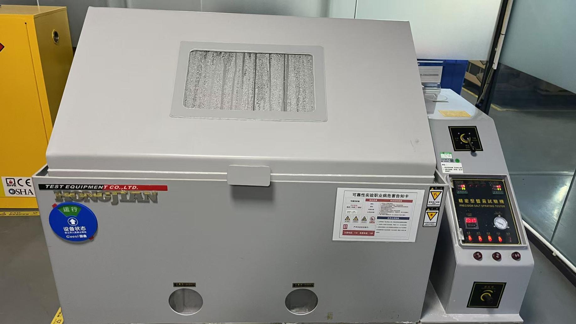
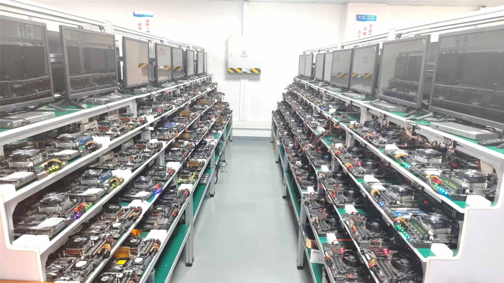
Our facility uses automated optical testing, interferometric end-face inspectors, and environmental stress chambers. Our 62-person quality control team tests every component, validating RJ45 jacks, modular magnetics, and high-frequency SFP+ transceiver modules to ensure low insertion loss and high system reliability.
With an annual export revenue of roughly USD 9.5 million, we serve major telecom providers and enterprise networks in North America, Europe, Japan, and Southeast Asia. We work with over 1,450 supply chain partners to secure quality raw materials. Our 240+ R&D engineers keep us at the forefront of network trends, launching approximately 180 new products each year to match evolving industry requirements.
Analyzing key drivers of data growth and physical layer validation requirements worldwide.
Modern data centers demand low latency and high bandwidth. As they transition to 400G and 800G architectures, even minor physical layer defects can degrade performance. Specialized cable and transceiver testing helps guarantee that fiber trunks and copper interconnects meet strict bit-error-rate (BER) thresholds.
Factory floors present harsh, noisy environments filled with electromagnetic interference (EMI). Cable verification in industrial settings must validate shielding performance and check for crosstalk. Our shielded RJ45 modules and high-precision testing routines ensure reliable communication in electro-mechanically active production areas.
Municipal networks and FTTx architectures span long distances across varied climates. Deploying these networks requires rugged test instruments. Our devices allow field engineers to verify optical power levels and copper termination paths under extreme real-world conditions.
Modern cable certifiers use high-frequency signals to map the electrical properties of copper links. By using Time-Domain Reflectometry (TDR), the tester sends a electrical pulse down the copper pairs and monitors the reflections. Impedance changes caused by kinks, poor terminations, or damaged conductors reflect energy back to the source. The tester calculates the time delay of these reflections to locate cable damage within centimeters.
When validating Category 6A or Category 8 runs, the tester measures Near-End Crosstalk (NEXT) and Far-End Crosstalk (FEXT). The high frequency of Cat8 (up to 2 GHz) can easily leak signal energy between adjacent pairs. Test tools measure this leakage to ensure the installation maintains adequate Signal-to-Noise Ratio (SNR) for 25GBase-T and 40GBase-T data transfers.
Furthermore, testing PoE++ (up to 90W/100W under IEEE 802.3bt) requires checking for DC resistance unbalance within and between pairs. High unbalance results in uneven current distribution, causing transformer saturation and signal degradation, which can lead to dropped packets.
As telecom architectures migrate to fiber-to-the-antenna (FTTA) and fiber-to-the-home (FTTH), hybrid optical-copper links have become common. In these setups, copper conductors deliver power while optical fibers handle high-speed data. Testing these networks requires a multi-faceted approach.
Fiber verification uses an Optical Power Meter (OPM) and a Visual Fault Locator (VFL) to check insertion loss and trace path breaks. Advanced setups also include Optical Time-Domain Reflectometry (OTDR) to identify backscattering events along the fiber link.
For the copper components, technicians must verify electrical parameters to prevent power delivery issues. Our modular RJ45 sockets, magnetic couplers, and active optical transceivers are designed to work together, maintaining high signal integrity and low insertion loss across these hybrid configurations.
Developing next-generation physical layer verification technologies for the networks of tomorrow.
We are integrating AI routines directly into our test firmware. Rather than simply displaying raw failure data, our next-generation software analyzes impedance sweeps to suggest specific troubleshooting steps, such as recrimping a connector or replacing a segment.
Our upcoming testing platforms will feature direct cloud integration. Field technicians can sync test results from their devices via Wi-Fi, allowing managers to generate compliance reports and verify installation quality in real-time.
As IoT devices require more power, we are expanding our testers to support active load testing for 90W PoE++ and higher. This validates that the structured cabling can sustain power transmission without overheating or dropping voltage.
FiberQ products comply with international regulatory and certification frameworks. Our structured cabling components and test methodologies meet standard industry requirements, including:
Our network validation tools and high-speed interconnects perform reliably across diverse settings:
In-depth explanations of critical physical layer metrics and testing methodologies.
Permanent Link Testing measures the installed horizontal cabling, including the wall outlet, bulk solid cable, and the patch panel jack. This test excludes the user-facing patch cords at both ends. It represents the standard for fixed infrastructure. Channel Testing, by contrast, includes the user patch cords connected to the active switch and terminal station. Certifiers use different adapter heads for each mode to account for patch cord attenuation.
A TDR diagnostic tool sends a high-frequency electrical pulse down the copper wire. The pulse travels at a speed determined by the cable's Velocity of Propagation (NVP). When the pulse hits a fault, such as a short circuit, an open path, or an impedance mismatch, part of the signal's energy reflects back. By measuring the time it takes for the reflected wave to return, the tester calculates the exact distance to the fault using the equation: Distance = (NVP × Speed of Light × Time Delay) / 2.
As transmission frequencies increase—up to 500 MHz for Cat6A and 2,000 MHz for Cat8—the electromagnetic fields around copper pairs grow stronger. Near-End Crosstalk (NEXT) measures the signal leakage from one pair to another at the end where the signal is transmitted. High NEXT can distort data, resulting in packet retries and lower transmission speeds. Proper twisting of copper pairs and effective shielding (F/UTP or S/FTP configurations) help minimize NEXT, which testers verify across the entire frequency range.
Under IEEE 802.3bt, PoE++ delivers up to 90W of power by sending current across all four copper pairs. If there is a difference in resistance between the conductors of a pair (DC resistance unbalance), current will flow unevenly. This unbalance can saturate the transformers in active switches and endpoints, leading to Ethernet signal distortion. Testing for resistance unbalance ensures the cable runs can support high-power PoE applications safely.
Basic (Tier 1) fiber certification measures insertion loss (the drop in light power along the fiber path) and polarity (ensuring the transmitter at one end connects to the receiver at the other) using an Optical Power Meter (OPM). Advanced (Tier 2) testing adds an Optical Time-Domain Reflectometer (OTDR) to evaluate local faults like splice points, connectors, and macro-bends, showing how loss is distributed across the link.
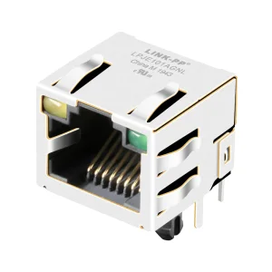
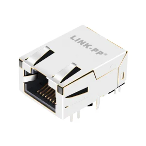
Shielded RJ45 connectors feature a metal wrap that acts as a Faraday cage when grounded. This shield blocks external electromagnetic fields (EMI) and radio frequency interference (RFI) from corrupting the internal conductors. In industrial networks or dense cable trays, shielded connectors are essential to prevent alien crosstalk from adjacent cabling runs.
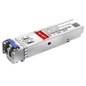
In most switches, 1G SFP transceivers can be used in 10G SFP+ slots, provided the port is configured to run at 1G speed instead of 10G. However, SFP+ transceivers cannot work in standard 1G SFP slots, as 1G interfaces lack the data processing capabilities required for 10G rates. Verifying these configurations with a protocol analyzer or link tester helps avoid link mismatches.
Return Loss is the ratio of reflected signal energy to the original transmitted signal. It is caused by variations in the cable's characteristic impedance. Common causes include bent cables, poorly matched connectors, or moisture in the wire pairs. High return loss can degrade signal quality, which is why testing for RL is standard when certifying high-speed network cabling.
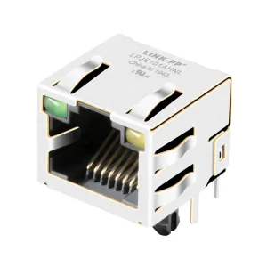
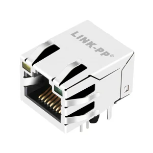
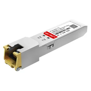
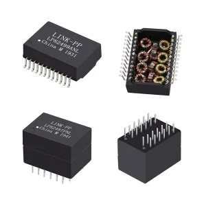
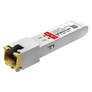
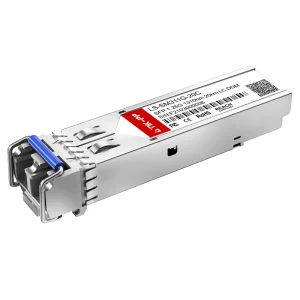
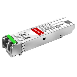
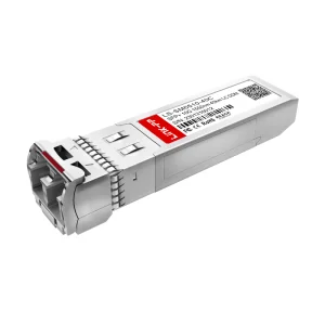
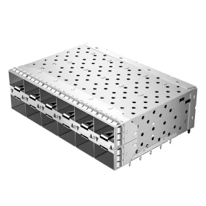
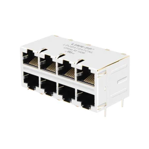
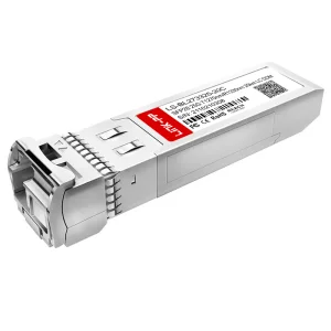
Active transceivers, low-profile sockets, and optical components designed for high-density networking and datacenter environments.
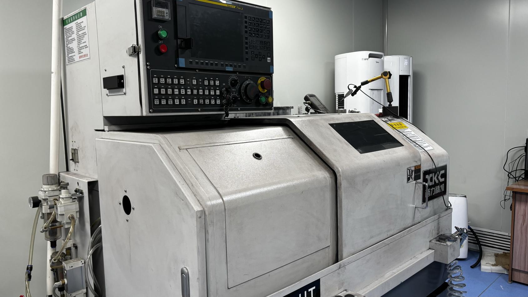
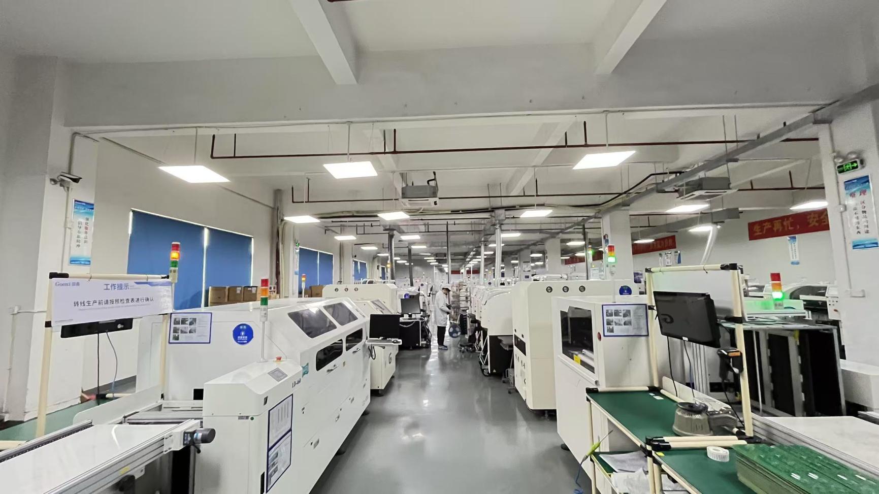
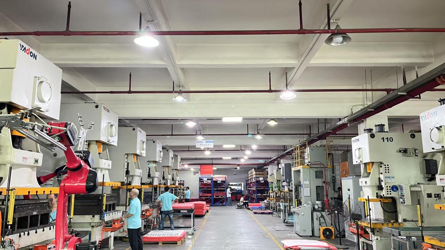
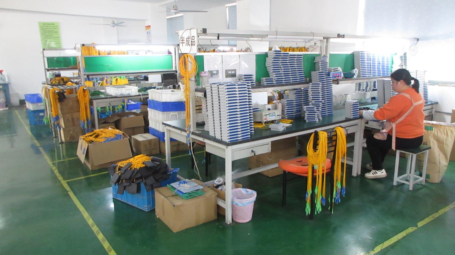
A inside look at our 12,600㎡ facility, showing the assembly, testing, and shipping processes behind our products.