FiberQ
FiberQ
FiberQ
Direct supply options for enterprise networking, high-speed SFP modules, and integrated magnetics RJ45 couplers.
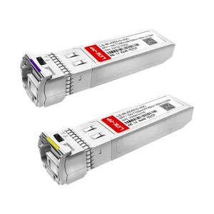
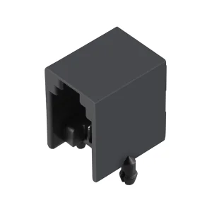
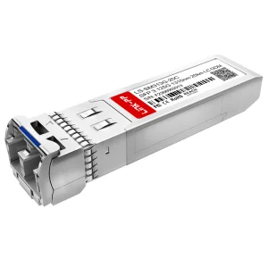
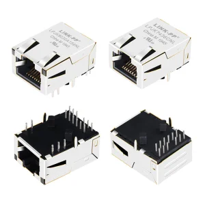
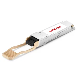
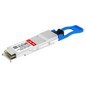
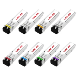
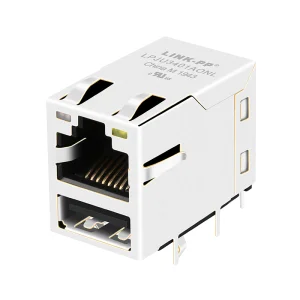
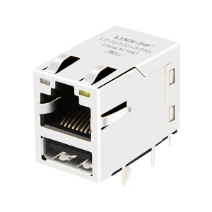
In modern Ethernet infrastructures, the physical layer (Layer 1) remains the foundation of all digital data transmission. As data centers, industrial automations, and telecommunication architectures transition to higher bandwidth and density, diagnostics at the physical port level become critical. The RJ45 connector with integrated LEDs (often featuring built-in electromagnetic interference shielding and integrated magnetic isolation, i.e., Magjacks) plays a dual role: providing mechanical and electrical connectivity while delivering immediate visual diagnostics of line status, speed, and network health.
This industry whitepaper provides network engineers, hardware design architects, and global procurement directors with an exhaustive directory of the top RJ45 connector and LED-integrated Ethernet port manufacturers. We will explore technical specifications, physical parameters, global supply chain structures, and validation protocols crucial to establishing high-efficiency OEM/ODM partnerships.
Evaluating an industrial-grade Ethernet connector manufacturer requires measuring strict electro-mechanical parameters to ensure long-term stability and reliability in demanding environments.
High-reliability applications demand that connectors sustain thousands of mating cycles without increased contact resistance or degradation of signal paths. Sourcing departments must move beyond simple pricing metrics and demand validation reports based on standard testing methods.
| Evaluation Parameter | Standard Specification (Enterprise Grade) | Testing/Compliance Method |
|---|---|---|
| Mating Cycles & Durability | Minimum 750 mechanical mating cycles | IEC 60603-7 compliance validation |
| Contact Plating Quality | 30u" to 50u" Selective Gold Plating over Nickel | X-Ray Fluorescence (XRF) thickness mapping |
| LED Operational Lifespan | >100,000 continuous operating hours | High-temperature operating life (HTOL) testing |
| Dielectric Withstanding Voltage | 1500V AC minimum (RMS, 60Hz, 1 min contact-to-shield) | IEEE 802.3 electrical isolation isolation test |
| Housing Flammability Rating | UL 94 V-0 Thermoplastic (e.g., LCP or Nylon-9T) | Vertical burning validation checks |
| Crosstalk & Insertion Loss | Max -1.0dB insertion loss (1-100MHz range) | Vector Network Analyzer (VNA) sweeping |
When selecting a factory, validating their in-house automated testing capability is crucial. Top suppliers utilize high-speed CCD visual inspection systems to identify coplanarity deviations of SMT solder tails, ensuring error-free PCB assembly. Additionally, automated testing fixtures verify the LED polarities, forward voltages, and light intensity metrics during assembly.
A granular look at the mechanical packaging, signal isolation circuitry, and optical coupling designs that prevent high-frequency noise interference.
The consolidation of the RJ45 jack, status indicator LEDs, and magnetic isolation transformers into a single component introduces dense signal integrity and physical routing challenges. Cross-talk and electromagnetic interference (EMI) are major failure modes in high-speed data transmission lines. Design engineers must examine the routing of the LED leads within the connector housing.
Because LEDs operate on DC drive currents (typically 20mA), the power lines carrying these signals can act as miniature antennas, picking up high-frequency noise from adjacent differential pairs (Tx/Rx lines). High-tier factories design their connectors with specialized metallic internal shield plates that separate the LED wiring path from the signal contacts. This architecture minimizes Near-End Crosstalk (NEXT) and Far-End Crosstalk (FEXT) in Multi-Gigabit networks (such as 2.5G and 10G Base-T setups).
Furthermore, the outer metal shell provides critical Faraday cage shielding. The configuration of grounding tabs (or "EMI fingers") on the top and sides of the connector shell maintains a low-impedance ground path to the system chassis. Proper selection of LED configurations—such as dual-color LED systems (e.g., Green/Yellow, Red/Green) with shared cathodes or anodes—allows motherboard designs to save trace routing space while conveying complex status information (such as Link/Activity, speed profiles, and fault codes).
Understanding the core specialization and capabilities of the leading industrial connector and optoelectronic component suppliers globally.
The manufacturing ecosystem for RJ45 connectors with integrated LEDs is divided between high-precision global brands and highly agile, vertically integrated Asian manufacturers that specialize in customized high-volume orders. Below, we profile the top ten global hubs and factories:
For enterprise-grade networks, choosing a supplier with robust mechanical validation systems is essential. Mid-to-long-term performance hinges on contact geometry design, plastic housing mold tolerances, and LED die sourcing consistency.
Analyzing how different industries configure LED-integrated RJ45 modular jacks to solve unique environmental and signal diagnostics challenges.
Understanding user intent and actual field usage reveals that RJ45 requirements vary dramatically depending on the operating environment. Below are four key scenarios:
In high-density top-of-rack (ToR) switches and patch panels, space is at a premium. Hardware designers rely on low-profile, ganged (multi-port) RJ45 connectors with integrated light pipes rather than physical LEDs. Light pipes channel the light from surface-mounted LEDs on the main PCB to the port interface, saving vertical board height. These systems run alongside ultra-high-speed transceivers (such as 100G/200G/400G QSFP cages) to provide reliable out-of-band management access ports.
On factory floors operating under the EtherCAT or Modbus TCP protocols, heavy industrial machinery generates severe EMI. RJ45 connectors here must feature robust shielding with high-grade metal shrouds. The integrated LEDs are critical for field technicians: a solid green light indicates a established hardware link, while a flashing yellow LED signals diagnostic data transmission. Suppliers for this sector must use specialty polymers like LCP (Liquid Crystal Polymer) to withstand reflow soldering temperatures up to 260°C and maintain mechanical integrity under high vibration.
Modern smart buildings utilize PoE to power security cameras, wireless access points, and LED lighting nodes. Passing up to 90W of DC power over Ethernet cables generates localized heat within the connector. The RJ45 jack must feature specialized internal contacts that prevent electrical arcing upon mating and unmating. Crucially, the LEDs must be optically and electrically isolated from the PoE power rails to prevent high voltages from damaging diagnostic circuits.
Outdoor cellular base stations require connectors rated for extreme thermal cycling (-40°C to +85°C). Here, waterproof sealing (IP67/IP68) is non-negotiable. Manufacturers design customized waterproof housing assemblies around the LED RJ45 jacks, using specialized gaskets and resin potting to prevent moisture from corroding the LED leads and connection terminals.
Exploring the next generation of physical layer connectivity, high-frequency signal design, and automation-aligned packaging.
As networks evolve from 1G copper interfaces to Multi-Gigabit (2.5G, 5G, and 10G Base-T) infrastructures, the design limits of RJ45 contacts are being pushed to their boundary. Standard RJ45 connections suffer from high return loss at frequencies above 250 MHz. Future roadmaps show factories redesigning contact shapes to optimize impedance matching and minimize signal reflection.
Another emerging trend is the Smart Diagnostic Interface. Instead of simple single-color status indicators, future connectors will integrate micro-controllers or smart driver chips directly within the RJ45 housing. These chips can cycle multi-color RGB LEDs to represent specific network health alerts, bandwidth bottlenecks, or physical cable faults, bypassing the need for complex software dashboards.
Simultaneously, the demand for eco-friendly electronics is forcing manufacturers to transition to halogen-free materials and lead-free soldering processes. Compliance with RoHS 3 and REACH regulations has become a baseline requirement for any supplier selling into Europe and North America.
Leveraging Chinese manufacturing scale, engineering ecosystems, and direct supplier integration for custom product developments.
The global electronic components supply chain relies heavily on production clusters in mainland China, particularly in the Guangdong, Zhejiang, and Jiangsu provinces. These manufacturing hubs house extensive ecosystems for precision molding, metal stamping, LED chip packaging, and high-frequency testing. This proximity allows factories to execute rapid design iterations, moving from initial CAD concepts to production-grade tooling in as little as 3-4 weeks.
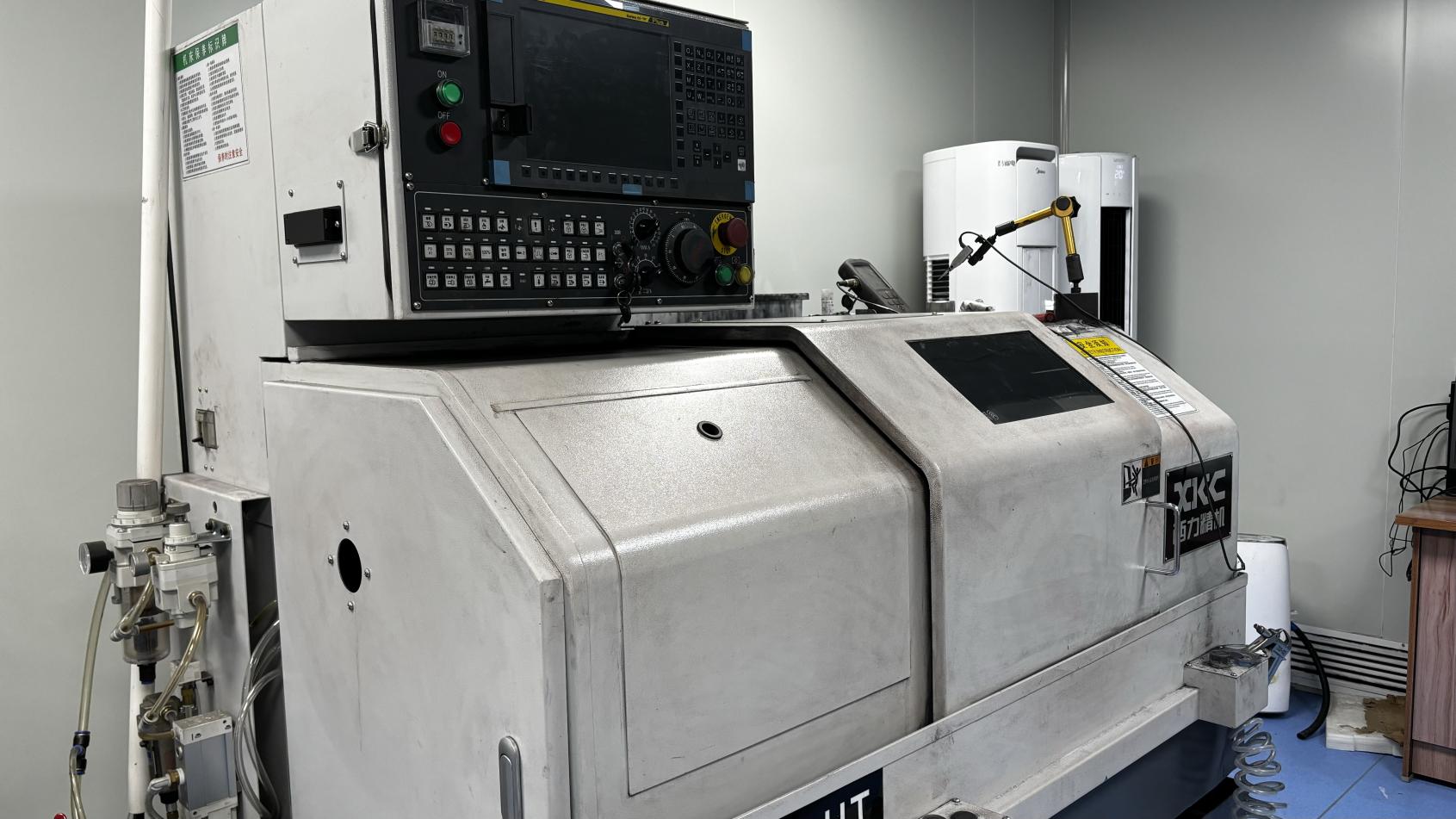
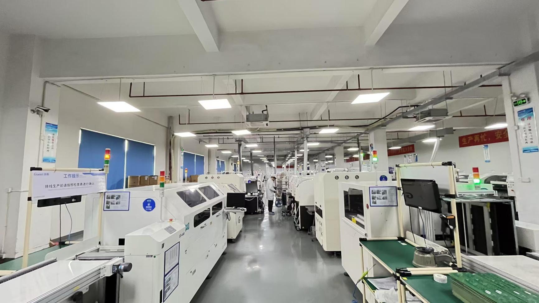
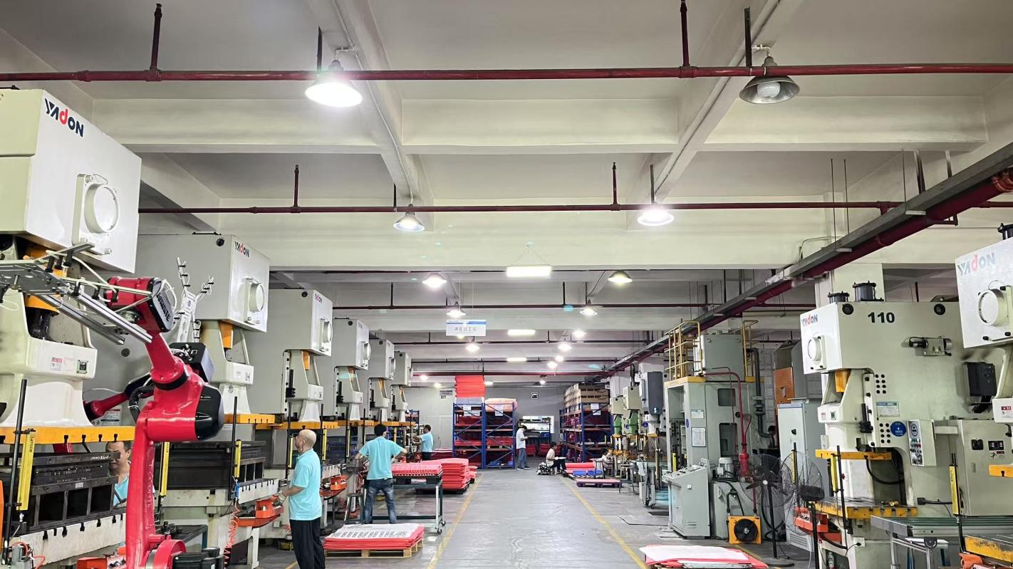
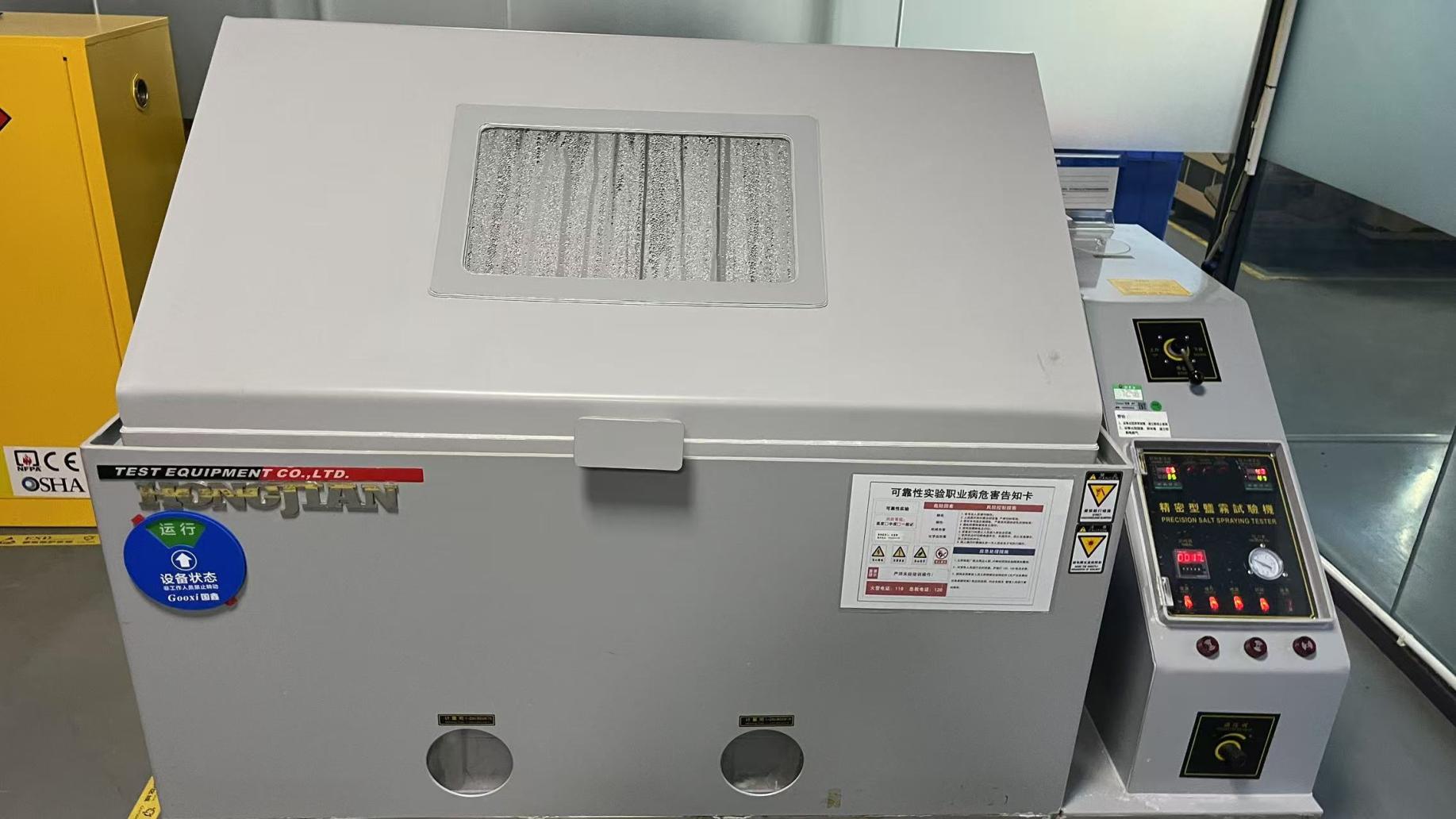
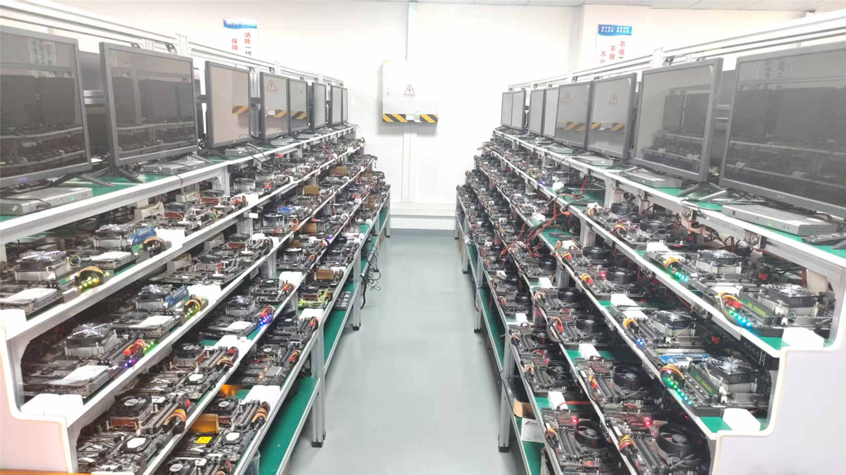
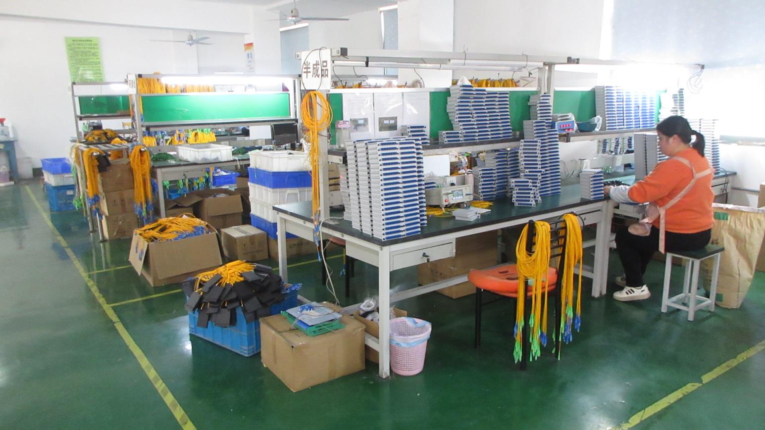
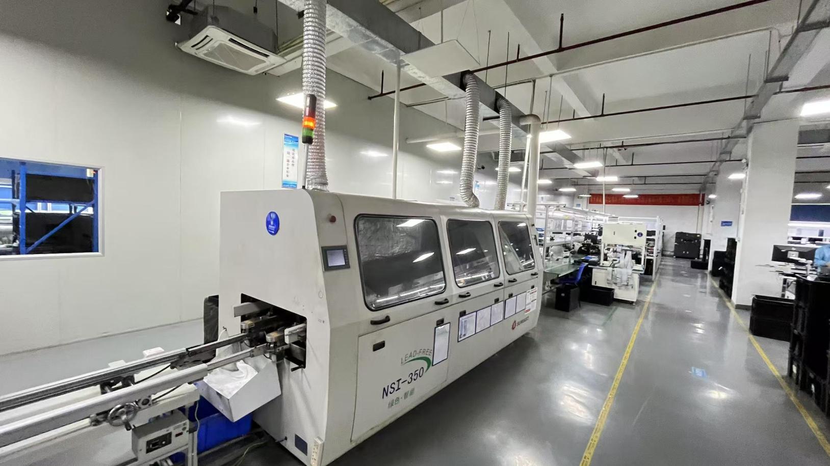
A prime example of this industrial scale is FiberQ Photonics Technology Co., Ltd. Established in 2015, FiberQ has grown into a highly reliable manufacturer, boasting 12 years of industry experience and 6 years of international trade history. Operating a 12,600㎡ modern manufacturing center, the company collaborates with over 1,450 supply chain partners to secure premium raw materials (such as high-grade engineering plastics and high-purity phosphor bronze terminals).
Supported by a robust engineering team of approximately 240 R&D experts, FiberQ offers end-to-end ODM/OEM capabilities. Their capability spans mechanical design, wavelength optimization, and signal integrity simulations. Over the past year alone, FiberQ introduced 180 new products to meet the changing needs of telecom carriers, system integrators, and data center operators worldwide.
Contact our technical sales team for custom SMT pin layouts, LED configurations, and shielding options.
Common questions from hardware layout designers and component sourcing specialists when integrating LED-equipped RJ45 jacks.
A1: The LED power supply lines operate on DC, but they are physically close to high-frequency differential signal lines. Without proper design, they can coupling noise. Quality manufacturers use internal metallic Faraday shields to isolate the LED leads from the data pins, minimizing noise coupling. Using bypass capacitors (typically 0.1µF) close to the LED pins on the host board helps suppress transient noise.
A2: Thicker gold plating (such as 30u" or 50u" gold) provides superior corrosion resistance against oxidation and humidity over time. In applications with high humidity or corrosive atmospheres (e.g., coastal facilities or chemical factories), lower plating thickness (such as 3u" or flash gold) can degrade rapidly, leading to intermittent connection dropouts and increased contact resistance.
A3: Yes, but the connector must be specifically rated for PoE, PoE+, or PoE++. Passing high currents through standard pins causes thermal buildup. Ensure the manufacturer validates the thermal performance under maximum load and that the diagnostic LEDs are electrically isolated from the power-delivery paths to prevent damage.
A4: Light pipes are solid plastic structures that route light from surface-mounted LEDs on the PCB to the front of the connector. This removes electrical LED circuits from the connector body, simplifying design, reducing EMI, and improving reliability since there are no LED leads inside the RJ45 housing that could fail due to mechanical stress.
A5: SMT (Surface Mount Technology) is ideal for automated, high-volume production but offers lower mechanical strength. Through-hole (DIP) mounting provides much stronger mechanical anchoring to the PCB, making it the standard choice for ports subjected to frequent user insertions and extractions. Press-fit technology offers high mechanical stability without the thermal stress of soldering, which is ideal for backplanes and dense ganged configurations.
SFP cages, specialized optical transceivers, low-profile RJ45 network jacks, and IP-rated waterproof modular connectors.