FiberQ
FiberQ
FiberQ
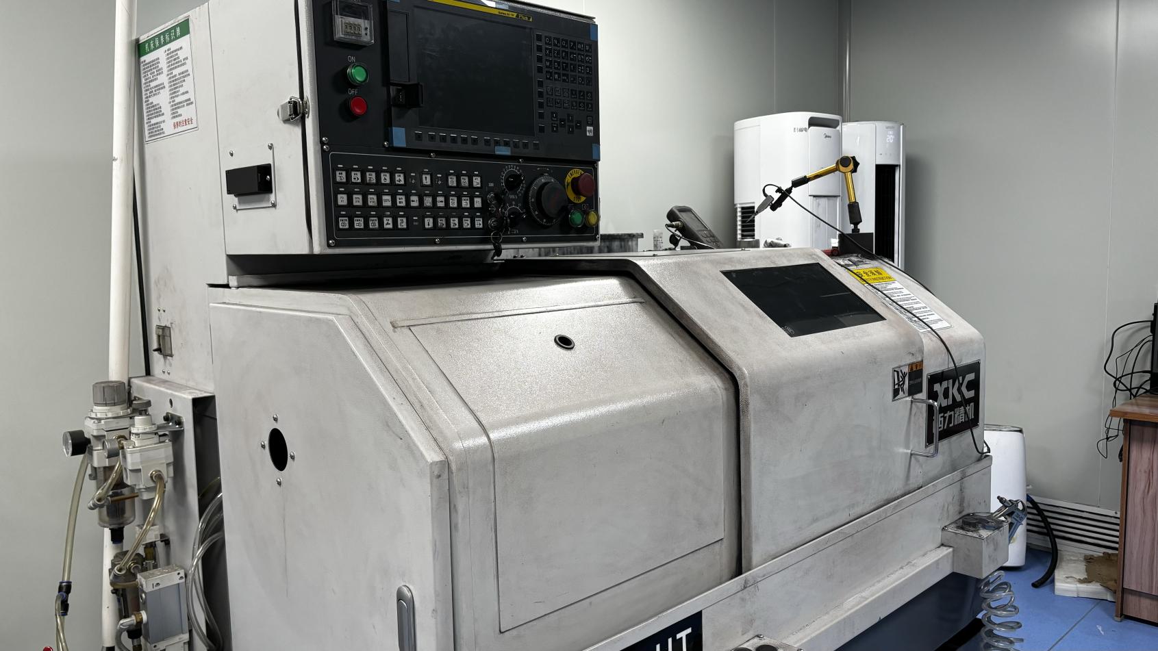
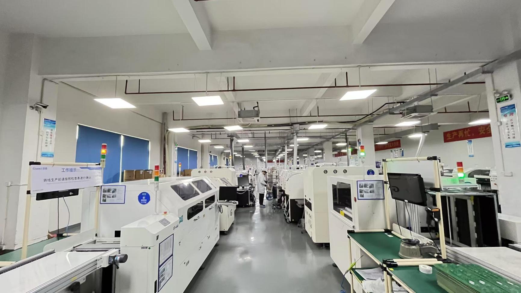
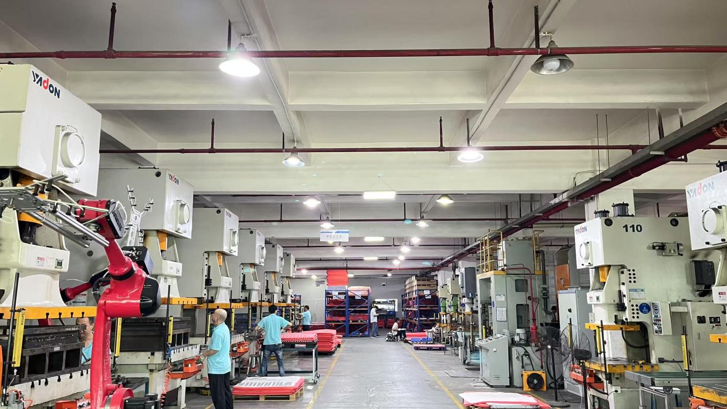
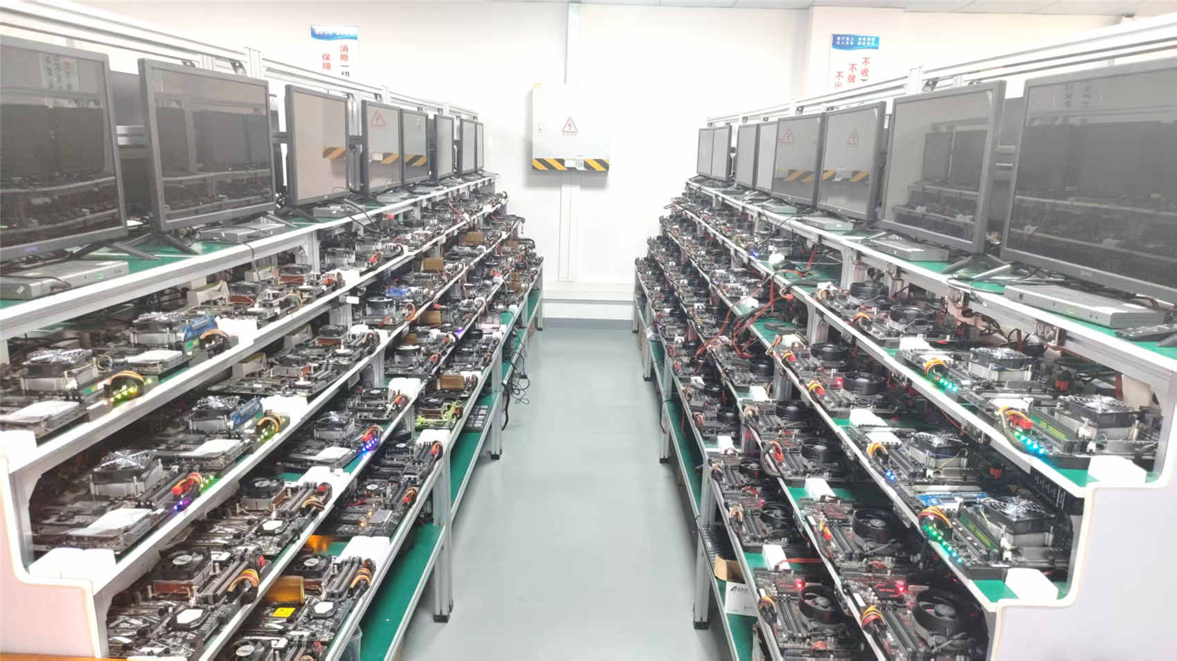
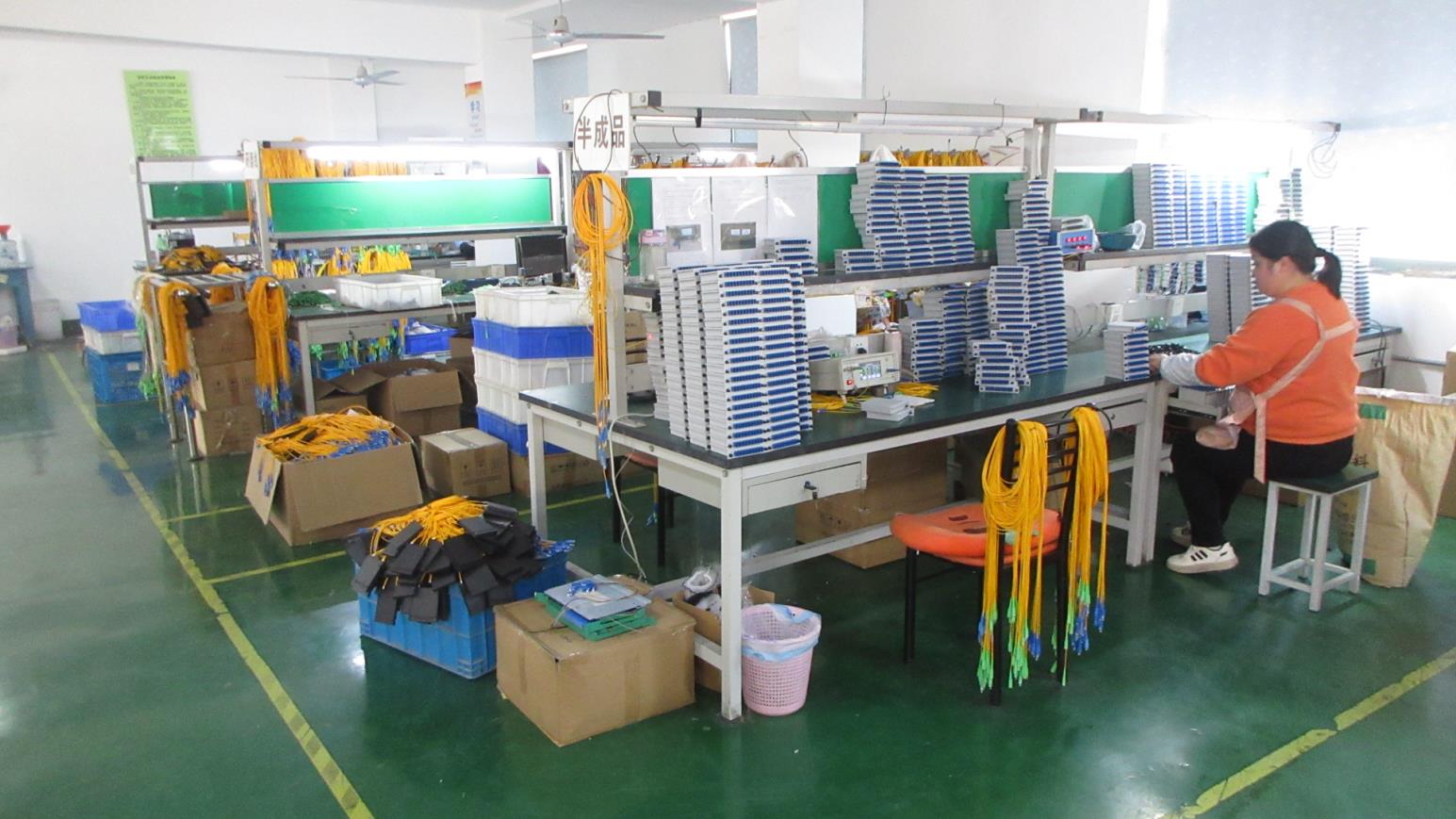
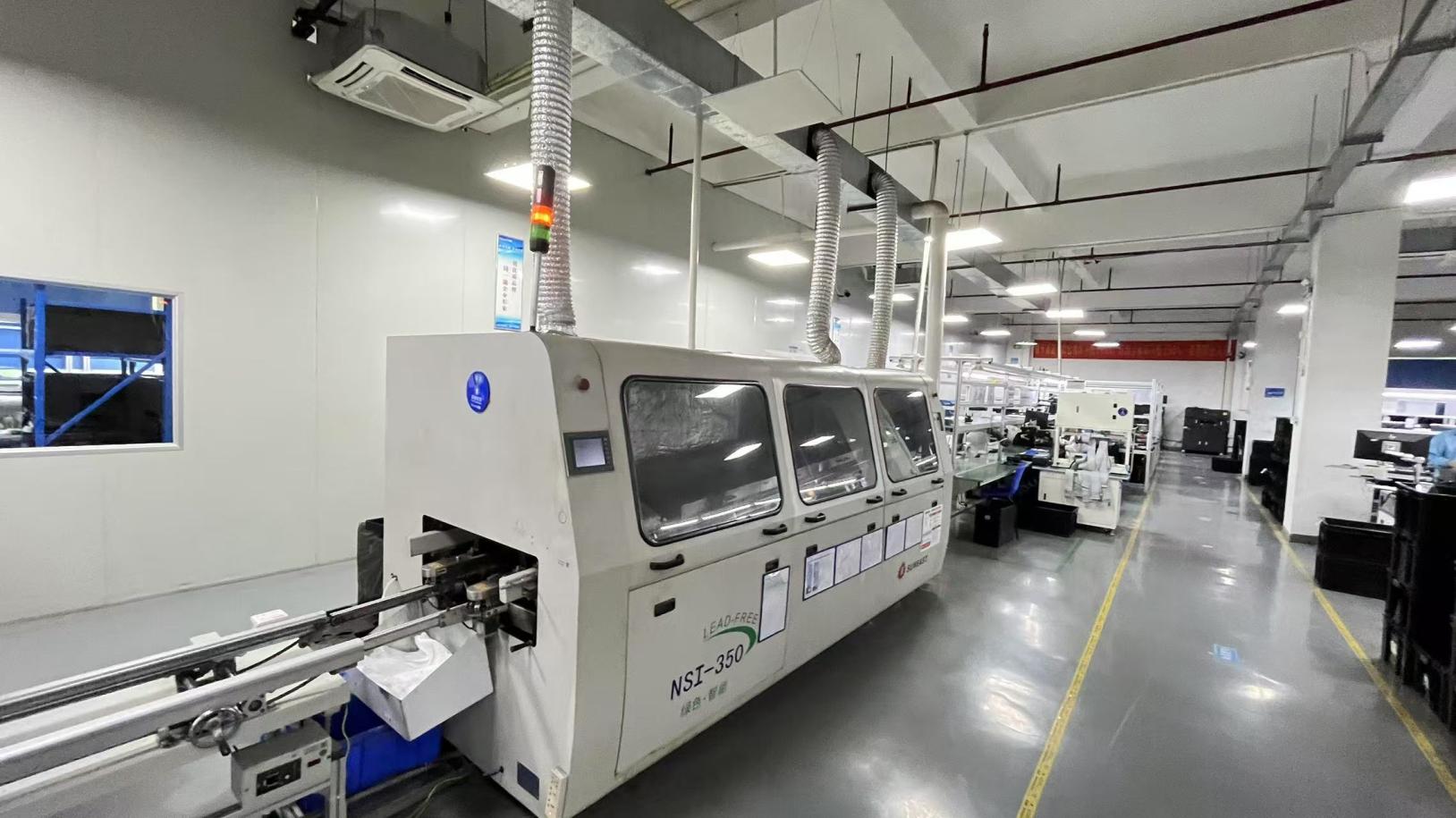
Modern Production Facility
Dedicated R&D Engineers
QC Inspection Experts
Supply Chain Partners
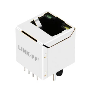
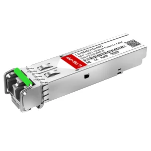
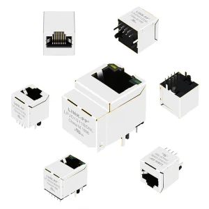
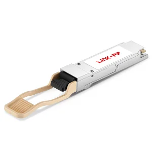
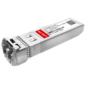
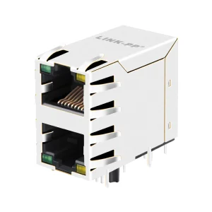
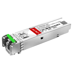
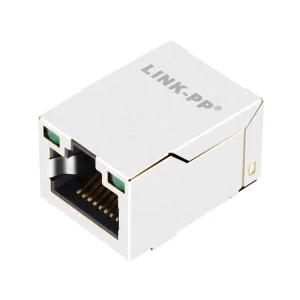
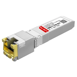
In the rapidly advancing telecommunications landscape, network design engineers demand interconnect hardware that bridges copper performance limits and optoelectronic efficiency. FiberQ Photonics Technology Co., Ltd. (founded in 2015) stands at the intersection of high-speed copper and optical technology. Specializing in advanced fiber optic transceivers alongside an elite range of RJ45 Connector Kits, magnetic modular jacks, and shielding structures, we facilitate high-performance copper interconnects for data centers, telecom networks, and high-frequency edge computing environments.
Operating a state-of-the-art 12,600 square-meter production facility, FiberQ has expanded from a local innovator to a dominant global supplier, backed by over 12 years of industry expertise and a 6-year footprint in rigorous international export channels. With annual export revenues exceeding $9.5 million, FiberQ has engineered custom physical-layer configurations for the world's most demanding carrier infrastructures, maintaining high signal fidelity and reliable electro-magnetic shielding.
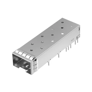
Every single batch of our RJ45 Connectors and SFP cages undergoes advanced optoelectronic and mechanical analysis. Utilizing automated optical testing (AOI), interferometric facet inspection, and structural scanning, we guarantee zero-defect contact alignments, minimizing return loss and contact resistance at critical interfaces.
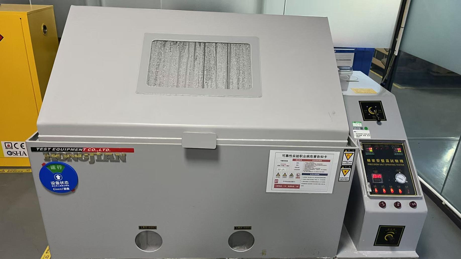
Our validation process integrates high-temperature aging chambers and environmental stress test models. Through thousands of insertion cycles under operating temperatures ranging from -40°C to +85°C, our connectors remain structurally intact, keeping insertion loss degradation within 0.2dB.
Equipped with an independent quality assurance division of 62 highly experienced test inspectors, we oversee product performance from raw material alloy sourcing up to final shipment packaging, ensuring alignment with FCC Part 68 subpart F and IEC 60603-7 standards.
High-speed data packet transfers over copper interfaces face signal degradation challenges, mainly due to near-end crosstalk (NEXT), far-end crosstalk (FEXT), and electromagnetic interference (EMI). A premium RJ45 connector kit is no longer just a plastic housing; it is an engineered component optimized for specific frequency profiles.
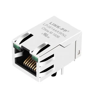
For instance, when managing Cat5e, Cat6, or Cat6a bandwidths, physical layout characteristics determine the transmission quality. Integrated magnetics (also known as Fastjacks) incorporate tiny toroidal transformers directly inside the connector housing. These integrated components suppress common-mode noise, provide electrical isolation, and match the impedance of the physical layer (PHY) chip, shielding critical components from spikes and ground loop discrepancies.
Manufacturing reliable components at a global scale requires both advanced technical engineering and supply chain resilience. Through our network of approximately 1,450 partner suppliers, FiberQ manages every stage of production—from raw copper purification and polymer compounding to precision plastic molding and high-speed automated pin insertion.
Located in China's advanced electronics manufacturing cluster, our facilities benefit from concentrated supply ecosystems. This allows us to source specialized tooling, custom LED dies, and high-permeability magnetic cores with short lead times. By consolidating advanced injection molding, automated SMT lines, and robotic soldering in one facility, we minimize manufacturing bottlenecks and reduce costs, translating to competitive pricing for global OEMs and ODMs.
Our tooling workshop produces multi-cavity injection molds with tolerances under ±0.01 mm. This high precision prevents coplanarity deviations in surface-mount (SMT) RJ45 connectors, ensuring consistent solder paste thickness during client assembly operations.
Our network of 1,450 suppliers ensures stable sourcing of core components. If market shifts restrict materials like high-grade phosphor bronze or nickel shielding sheet stock, our backup sourcing protocols keep high-volume production lines running smoothly.
With an annual export base of $9.5 million and high automation, our production floor easily handles sudden increases in volume, scaling up from prototype runs to million-unit monthly shipments for global rollouts.
Off-the-shelf connectors often fall short for specialized system designs. Hardware developers face issues like tight PCB heights, custom board layouts, or specific EMI footprint constraints. FiberQ provides full engineering customization, backed by 240 R&D engineers who design tailored products, simulate signal behavior, and verify component reliability.
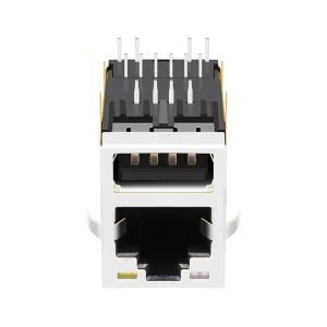
In the past year alone, our engineering team developed and launched 180 new products, including low-profile multi-port vertical RJ45 jacks, hybrid USB-RJ45 stacked modules, and EMI-optimized SFP cages. We assist clients through every phase, from initial 3D CAD modeling and finite element analysis (FEA) to rapid prototyping and high-reliability testing.
Deploying equipment globally requires strict adherence to international regulatory frameworks. To support our clients' global operations, FiberQ products comply with main environmental and safety standards, including RoHS (Restriction of Hazardous Substances), REACH, and UL flammability specifications.
Additionally, we provide direct engineering support across our primary export regions, including North America, Europe, Japan, and Southeast Asia. Our field application engineering teams help clients navigate system compliance, resolve layout challenges, and conduct local EMI shielding testing to speed up time-to-market.
Meets FCC Part 68 guidelines for physical dimensions and gold plating thickness, and UL 94 V-0 requirements for flame resistance in high-density telecom equipment.
Full CE marking, RoHS conformity, and compliance with EN 60603-7 specifications, assuring safe and sustainable integration into public networks.
Conforms to Japanese VCCI compliance standards for electromagnetic compatibility, matching the strict high-reliability standards of Japanese industrial systems.
Our RJ45 connector kits and optoelectronic transceiver modules are engineered for durability, supporting high-speed networks across diverse vertical markets.
In high-density top-of-rack (ToR) switches and blade servers, our shielded SFP+ cages and high-performance RJ45 jacks ensure stable data transmission, minimizing packet loss in high-temperature, 24/7 processing environments.
For industrial PLCs, motor drives, and robotics, our ruggedized vertical jacks with integrated transformers resist electromagnetic noise, thermal shock, and vibration on the factory floor.
Installed in outdoor base stations and GPON/EPON optical network terminals (ONTs), our connectors handle environmental stress, providing long-term reliability for outdoor telecommunications infrastructure.
FiberQ maintains full control over quality and delivery schedules by using in-house tooling, high-precision automated manufacturing equipment, and strict validation labs.
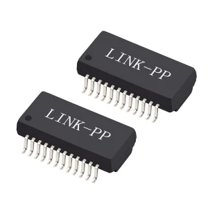
Integrated magnetics (also known as Fastjacks) incorporate isolation transformers and common-mode chokes directly into the connector housing. This setup saves PCB space, shields signal pathways from electromagnetic interference (EMI), and prevents common-mode noise issues that degrade data transmission.
Our R&D team designs the internal turns-ratio, inductance, and autotransformer configurations of our RJ45 connectors to match the requirements of major PHY semiconductor manufacturers, including Broadcom, Marvell, Intel, and Realtek.
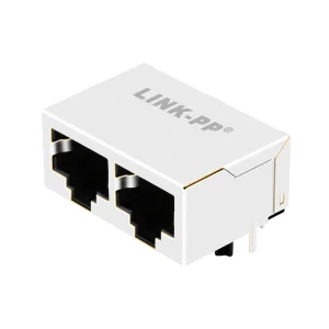
Yes. We offer complete custom tooling to adapt RJ45 connector dimensions, tab orientations (tab-up or tab-down), low-profile stack heights, SMT/through-hole mounting pins, and multi-port ganged configurations (e.g., 1x2, 2x2, 2x6) to fit specialized hardware layouts.
We use vector network analyzers (VNAs) to measure insertion loss, return loss, near-end crosstalk (NEXT), and common-mode rejection up to high frequencies. This testing ensures compliance with Cat5e, Cat6, and Cat6a speed specifications.
We support green, yellow, orange, red, and blue LEDs, including single-color and bi-color integrations. We can also integrate current-limiting resistors inside the connector shell to simplify layout designs on your main PCB.
Yes. We design our magnetic windings and contact layouts to carry high DC currents (up to 1,000 mA per pair) without overheating or causing signal saturation, meeting IEEE 802.3at and 802.3bt performance standards.
Our ISO9001-certified factory uses automatic optical inspection (AOI) to verify SMT quality, high-speed dimensional scanners to check pin coplanarity, and automated functional testers to confirm turns ratio and isolation voltage on every shipping lot.
Standard modification prototypes (such as changes to LEDs or turns ratios) are usually delivered within 2 to 3 weeks. Full custom mold designs typically take 4 to 6 weeks, which includes 3D CAD reviews and initial test runs.