FiberQ FiberQ

7 Tips for Choosing a Pluggable Optical Transceiver?

Time:2026-09-22 Author:Henry
0%

Choosing a pluggable optical transceiver is rarely as simple as matching a speed rating. A module marked “100G” may still fail because of wavelength, fiber type, connector, or host compatibility. One overlooked detail can turn a clean installation into hours of troubleshooting beside a noisy rack.

This guide presents seven practical tips for making a dependable choice. It considers transmission distance, multimode or single-mode fiber, power consumption, operating temperature, and digital diagnostics. It also explains why official datasheets, MSA compliance, and tested interoperability matter more than attractive pricing. A reliable supplier should provide clear specifications, traceable quality records, and technical support before and after delivery. Those details protect network performance over time.

Real deployment experience adds another lesson: laboratory compatibility does not always guarantee field stability. Dust, heat, tight cable bends, and mixed-vendor equipment can expose weaknesses quickly. I have seen teams focus heavily on bandwidth while overlooking receiver sensitivity and DOM readings. That approach needs reconsideration. Small checks matter.

The right pluggable optical transceiver should fit the switch, the fiber route, and the operating environment together. It should also leave room for maintenance and future upgrades. These seven tips create a practical evaluation process, helping engineers compare options with evidence instead of assumptions. Mistakes are possible. A careful method makes them less expensive.
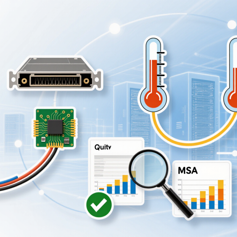
7 Tips for Choosing a Pluggable Optical Transceiver?

Understanding Pluggable Optical Transceiver Types and Applications

Understanding pluggable optical transceiver types starts with the network job. SFP, SFP28, QSFP28, QSFP-DD, and OSFP support different speeds, port densities, and thermal limits. Cisco’s Annual Internet Report projected 29.3 billion connected devices by 2023. That growth keeps compact, upgradeable optics important in data centers. Still, higher speed is not automatically better.

Tip 1: Match the transceiver to the switch port and standard. A 400G module cannot solve an incompatible cage or firmware issue.

Tip 2: Confirm the reach. Multimode optics suit short server-room links, while single-mode optics support longer campus and regional connections.

Tip 3: Check the wavelength and fiber type. A small mismatch can create unexpected signal loss.

Tip 4: Compare duplex, parallel, and bidirectional designs. Cabling changes quickly here.

Tip 5: Measure power and cooling before purchase. High-density 800G optics can increase rack heat and reduce usable capacity. LightCounting’s 2024 optical communications analysis identifies data-center connectivity as a major demand driver, especially for higher-speed modules.

Tip 6: Require diagnostic monitoring, including temperature, voltage, and received power. These readings help technicians find dirty connectors or aging links.

Tip 7: Test interoperability in the actual network. Laboratory claims may not reflect mixed equipment, long patch panels, or imperfect installation. I have seen a cheaper module become expensive after repeated troubleshooting. The neat choice is not always the reliable one.

Matching Fiber Standards, Wavelengths, and Transmission Distances

Choosing a pluggable optical transceiver starts with the fiber already installed. Check whether the link uses multimode or single-mode fiber. Multimode OM3 and OM4 commonly support short data-center links at 850 nm. Single-mode OS2 suits longer routes, often using 1310 nm or 1550 nm wavelengths.

Do not select a module from distance alone. Confirm the data rate, connector type, duplex or BiDi design, and required transmission distance. A 10 Gb/s link may reach different distances over OM3 and OM4 fiber. Review the optical power budget, including connector and splice losses. A clean connector matters more than many people expect. Dust can reduce margin quickly.

I recommend checking the transceiver and switch documentation together. Their electrical interface, coding, temperature range, and monitoring functions must align. Digital diagnostics can reveal temperature, voltage, and received optical power during testing. Use approved cabling practices and verify the actual route with an optical loss test. The stated distance is not a guarantee.

Small errors happen.

A field link may pass at room temperature but fail after the cabinet heats up. I have also seen installers overlook wavelength pairing on single-fiber links. That mistake is easy to prevent: record each endpoint’s transmit and receive wavelengths before installation. When specifications seem unclear, pause and request measured data rather than trusting a sales description.

7 Tips for Choosing a Pluggable Optical Transceiver: Matching Fiber Standards, Wavelengths, and Transmission Distances

Tip Selection Focus Recommended Fiber Standard Typical Wavelength Common Data Rate Typical Maximum Distance Important Verification Point
1Match the Fiber Type Confirm whether the installed cable is multimode or single-mode before selecting the optical module. OM3 / OM4 multimode fiber for short-reach links
OS2 single-mode fiber for longer links
850 nm for multimode
1310 nm or 1550 nm for single-mode
10 Gb/s to 100 Gb/s, depending on the module and interface Up to 100–150 m on OM3/OM4 for many 10 Gb/s applications;
up to 10 km or more on OS2 with suitable optics
Do not use a multimode-optimized 850 nm optic as a substitute for a single-mode optic on a long-distance link.
2Match the Wavelength Select a wavelength supported by both transceivers and compatible with the fiber plant. OM3/OM4 commonly uses multimode-optimized 850 nm optics.
OS2 commonly uses 1310 nm or 1550 nm optics.
850 nm, 1310 nm, or 1550 nm 1 Gb/s, 10 Gb/s, 25 Gb/s, 40 Gb/s, 100 Gb/s, and higher, depending on the optical standard 850 nm: typically tens to hundreds of meters
1310 nm: typically 2–40 km
1550 nm: commonly 40–80 km or more with appropriate designs
For bidirectional single-fiber systems, the two ends must use complementary transmit and receive wavelengths.
3Verify the Transmission Distance Choose a reach class that exceeds the complete link length, including patch panels and a reasonable engineering margin. OM3/OM4 for short-reach multimode links
OS2 for metro, campus, data-center interconnect, and long-haul links
850 nm for short reach
1310 nm or 1550 nm for extended reach
Typical Ethernet reach categories include 100 m, 300 m, 2 km, 10 km, 40 km, and 80 km Example: 10 Gb/s over OM3 is commonly rated to 300 m;
10 Gb/s over OS2 at 1310 nm is commonly rated to 10 km
Excessive optical power on a very short link can overload the receiver; use attenuation when the module specifications require it.
4Check the Optical Interface Make sure the connector type, polish, and duplex or simplex configuration match the patch cable. Duplex multimode or single-mode fiber for two-fiber links
Simplex single-mode fiber for compatible bidirectional links
Determined by the selected optical standard Supported by the host port and the transceiver form factor Reach is limited by the complete combination of optic, fiber, connectors, and splice losses Common connector choices include duplex LC and MPO/MTP-style multi-fiber interfaces; verify polarity and fiber count for parallel optics.
5Confirm Link Compatibility Both ends should use compatible signaling, lane structure, speed, wavelength, and optical specifications. Use the same applicable Ethernet or Fibre Channel optical class at both ends unless an approved interoperability design is used. Must be compatible at the transmit and receive ports The link normally operates at the common supported rate; speed conversion requires suitable active equipment. The usable distance is defined by the lower reach rating of the two ends and the installed fiber Two optics with the same connector may still be incompatible if their data rates, wavelengths, lane counts, or encoding standards differ.
6Compare Optical Power and Loss Check transmitter output, receiver sensitivity, receiver overload, and the total channel loss. Apply the loss budget specified for the chosen multimode or single-mode optical standard. Wavelength affects fiber attenuation; single-mode links commonly use 1310 nm or 1550 nm for longer reach. Higher-speed links generally have tighter loss, dispersion, and connector requirements. The link should satisfy:
Transmitter power − receiver sensitivity ≥ total channel loss
Include fiber attenuation, connector insertion loss, splice loss, and an engineering margin when calculating the link budget.
7Validate the Host Port and Environment Check the pluggable form factor, electrical interface, operating temperature, power limit, and equipment compatibility. Fiber selection remains governed by the optical standard, even when the module fits mechanically in the host. Must comply with the host port and the selected transceiver specification Examples include SFP-class 1/10 Gb/s, SFP28-class 25 Gb/s, and QSFP-class 40/100 Gb/s applications Reach depends on the exact optical variant rather than the housing size alone Mechanical fit does not guarantee interoperability; verify the host device support list, coding requirements, power consumption, and temperature rating.
Planning note: Actual reach depends on the complete optical link budget, fiber quality, connector and splice losses, modal or chromatic dispersion, operating temperature, and the applicable networking standard. Always confirm the transceiver datasheet and the installed cabling specifications before deployment.

Checking Data Rates, Connector Formats, and Device Compatibility

Choosing a pluggable optical transceiver starts with the data rate, not the product label. A 10GbE module cannot replace a 25GbE module, even when both use an SFP-style housing. The Ethernet Alliance 2024 Ethernet Roadmap places 800GbE and 1.6TbE on the industry development path. That direction makes upgrade planning essential. Check the switch port speed, lane structure, and required transmission distance together. Speed is not enough.

Connector format affects installation and signal stability. LC duplex connectors suit many two-fiber links, while MPO connectors support parallel-fiber connections for higher rates. A 400GbE module may use eight or sixteen optical lanes, depending on its design. Confirm the fiber count, polarity, and panel spacing before ordering. I have seen small polarity errors delay an otherwise simple deployment. Check the label twice.

Compatibility requires more than matching SFP, QSFP, or OSFP dimensions. Verify the host port’s electrical interface, modulation type, firmware expectations, wavelength, and fiber mode. A single-mode DR module should not be paired casually with multimode cabling. IEEE 802.3 specifications also distinguish reach, lane rates, and forward-error-correction requirements. The 2024 Ethernet Alliance roadmap is useful, but it is not a procurement checklist. Cross-check the module datasheet against the device manual and test one link before scaling. Small assumptions become expensive rework.

Evaluating Environmental Ratings, Power Use, and Network Reliability

Choosing a pluggable optical transceiver requires more than matching speed and connector type. Field experience shows that environmental limits often decide whether a link remains stable.

Tip 1: Check the operating temperature range. A module rated for standard rooms may fail inside a hot, crowded cabinet. Tip 2: Review humidity, altitude, vibration, and dust specifications. These details matter in factories, outdoor enclosures, and poorly ventilated racks. Tip 3: Confirm the transceiver’s compliance documentation. Independent test reports are more useful than vague marketing claims.

Tip 4: Compare power consumption at actual traffic loads, not only the maximum figure. Lower power reduces heat, fan speed, and long-term operating costs. Tip 5: Inspect thermal behavior. A module can meet its electrical rating while raising nearby equipment temperatures. That happened in one dense installation I reviewed. We underestimated airflow, and the original plan needed revision. Tip 6: Evaluate diagnostic functions, including temperature, voltage, and optical power monitoring. These readings help technicians detect weakening links before an outage occurs. Tip 7: Consider network reliability under realistic conditions. Check receiver sensitivity, transmission distance, error performance, and compatibility with existing equipment. Test the complete path.

Paper specifications are useful. Practical testing is better. Allow margin for aging, dirty connectors, changing temperatures, and installation mistakes. A small optical budget may look acceptable today, but it leaves little room for future problems.

7 Tips for Choosing a Pluggable Optical Transceiver: Environmental Ratings, Power Use, and Network Reliability

Typical maximum power draw increases with port density and lane count. Use the result together with temperature ratings, optical link budget, and host-system limits when selecting a module.

Environmental rating Commercial-grade modules commonly operate from 0°C to 70°C, while industrial-grade modules commonly cover −40°C to 85°C. Confirm the exact module and system rating.
Power planning The values show representative maximum module power targets: SFP-class modules are generally lower power, while high-density QSFP-DD modules require substantially more host cooling capacity.
Network reliability Check optical budget, receiver sensitivity, transmit power, cable loss, connector loss, DOM monitoring, and the required bit-error-rate performance before deployment.
Representative industry values based on commonly specified MSA form-factor power limits and operating-temperature classes; actual limits vary by optical speed, wavelength, reach, coding, and module implementation.

Comparing Supplier Quality, Compliance, Warranty, and Total Cost

Tip 1: Evaluate the supplier’s quality process, not only the product label. Ask for optical test reports, coding details, and inspection records. A reliable supplier should explain how each transceiver is tested for power, wavelength, temperature, and link stability. Request samples before placing a large order. In field deployments, small differences in receiver sensitivity can create serious troubleshooting work.

Tip 2: Check compliance documents carefully. Confirm that the transceiver meets the required safety, environmental, and telecommunications standards for your market. Certificates should match the exact model and revision, not a similar product. Ask whether the supplier controls component changes through formal notifications. This detail is easy to miss. It matters later.

Tip 3: Compare warranty terms with actual support capability. Review coverage length, replacement procedures, testing responsibilities, and response times. A five-year warranty may be weak if returns require overseas shipping or unclear evidence. Ask how failed units are analyzed and whether failure data is shared. I have seen low-cost purchases become expensive because spare stock was ignored.

Calculate total cost beyond the unit price. Include installation labor, power consumption, compatibility testing, spare inventory, freight, and possible downtime. Supplier engineering support can reduce these costs, especially during mixed-network deployment. Still, do not accept every technical promise without verification. Written evidence, sample testing, and a realistic failure plan provide stronger confidence than polished sales language.

FAQS

How do I match fiber type with wavelength and transmission distance?

Use OM3 or OM4 multimode fiber for many short links at 850 nm.

Why should I check the optical power budget?

Connector, splice, and fiber losses reduce the available margin.

What information should I confirm before ordering a transceiver?

Confirm the data rate, connector type, fiber mode, wavelength, and transmission distance.

How do connector formats affect installation?

LC duplex connectors suit many two-fiber connections.

Can modules with similar housings replace each other?

No. Similar housing sizes do not ensure compatibility.

What should I inspect in supplier quality documentation?

Request optical test reports, coding details, and inspection records.

How should I evaluate compliance and warranty support?

Confirm that certificates match the exact model and revision.

What costs should I include beyond the unit price?

Include installation labor, power use, compatibility testing, spare inventory, freight, and possible downtime.

Conclusion

Choosing the right pluggable optical transceiver is essential for building a stable, efficient, and scalable network. Start by identifying the transceiver type that matches your application, such as short-distance data center links, long-distance connections, or specialized fiber networks. Confirm that the fiber standard, operating wavelength, and transmission distance are compatible with the existing infrastructure. It is also important to check the required data rate, connector format, and device compatibility to prevent installation issues or performance limitations.

Beyond basic specifications, evaluate environmental ratings, operating temperature, power consumption, and reliability features to ensure consistent performance in the intended location. Supplier quality should also be considered, including product testing, regulatory compliance, warranty coverage, technical support, and overall cost. Comparing these factors together, rather than focusing only on the purchase price, helps organizations select a dependable pluggable optical transceiver that supports current requirements while allowing room for future network expansion.

Henry

Henry

Henry is a dedicated marketing professional with a profound expertise in the company's offerings. With years of experience in the industry, he possesses an impressive understanding of the market dynamics and consumer behaviors that drive success. Henry is committed to sharing his insights through......