FiberQ
Choosing an MPO optical transceiver is not just a matter of matching port speed. The connector, fiber type, polarity, reach, and loss budget must work together across the complete link. A mismatch can leave a high-speed link dark, even when every component appears compatible.
Industry references help narrow the choices. The Ethernet Alliance’s 2024 Ethernet Roadmap tracks the progression of Ethernet speeds, including 800 GbE and emerging 1.6 TbE work. IEC 61754-7 specifies the MPO connector interface, while LightCounting’s optical-transceiver market reports track demand and technology shifts across the sector. These sources offer useful context, but product compatibility still depends on the exact transceiver and cabling specifications. Check connector gender and keying, single-mode or multimode fiber, lane mapping, insertion loss, and the vendor’s interoperability guidance. Small details matter.
One limitation deserves honesty: no source material was provided for a verifiable, verbatim quotation from a named MPO optical transceiver expert. Inventing one would weaken the reliability of this guide. A practical field rule is simple: verify the full optical path, not just the module label. Before choosing, compare the datasheet with the switch requirements and the installed cabling, then confirm the link budget and polarity plan. The following seven tips turn those checks into a clear selection process.
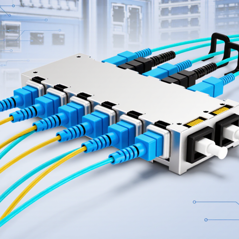
An MPO optical transceiver sends or receives several optical signals through a single multi-fiber connector. Many parallel-optics designs use separate fiber lanes, so the connector’s fiber count and lane arrangement must match the link. Small details matter. Check the module’s data sheet for supported fiber type, wavelength, speed, and reach before choosing one.
Think about the actual connection. A short data-center link between switches may use multimode fiber, while a longer route may require single-mode fiber. MPO polarity, connector key orientation, and pin configuration also affect whether the link works. A connector can fit physically and still be wired incorrectly. It is an easy detail to overlook, even on a well-planned installation.
The intended application determines whether you need a direct MPO-to-MPO connection or a breakout to several duplex links. Confirm that both endpoint devices support the same optical standard and lane configuration. Also check cable loss and the planned route, not just the distance on a floor plan. In practice, layouts change; leaving no room for testing or future moves can complicate an otherwise suitable choice. A careful match between transceiver, cabling, and equipment matters more than the connector shape alone.
Before choosing an MPO optical transceiver, check the exact port type and supported data rate on your equipment. A connector that fits does not guarantee that the link will work. Confirm the transceiver’s lane configuration and polarity requirements against the switch documentation. Check the fiber, too: multimode optics require a compatible multimode grade, while single-mode optics need single-mode fiber. Mixing them can cause weak or absent links. Small details matter.
Then verify the MPO connector itself. Match the fiber count, key orientation, and pin configuration specified for the transceiver and cable. Some MPO connectors have guide pins; others do not. Check both ends, not just the visible plug. Also confirm that the cable’s polarity method matches the equipment’s lane mapping. A common oversight is assuming every MPO trunk uses the same arrangement. It is an easy mistake to make, and port labels are not always clear. If specifications leave room for doubt, ask the equipment supplier or a qualified fiber technician to confirm the complete link before installation. A quick inspection under good lighting can catch a damaged or dirty endface, but it cannot replace compatibility checks.
Choosing an MPO optical transceiver starts with the link’s required data rate. Check the switch port speed, lane count, and intended breakout arrangement; matching connector shape alone is not enough. For example, a parallel-optics link may use multiple fiber lanes, while a breakout setup sends lanes to separate ports. Confirm that both ends support the same rate and lane mapping.
Next, compare reach and wavelength against the actual fiber path. A short link inside one rack may need different reach specifications from a connection crossing a building. Check the installed fiber type, patch panels, and total distance, then confirm both transceivers use compatible wavelengths. Small details matter. A mismatched fiber grade or an overlooked patch cord can undermine an otherwise suitable link.
Finally, review optical performance, not just headline speed. Compare transmit power, receiver sensitivity, and the link’s loss budget with the expected connector and cable losses. Keep MPO end faces clean, and verify polarity and alignment before installation. This detail is easy to miss. A datasheet can look reassuring, yet real-world performance depends on the complete optical path. Leave some margin where possible, and validate the link with measured readings rather than assumptions.
Compare data rate, reach, wavelength, and optical performance before selecting a transceiver.
The chart compares typical maximum reaches for parallel multimode Ethernet optics: 40GBASE-SR4 and 100GBASE-SR4 operate at 850 nm with MPO-12 connectivity, while 400GBASE-SR8 operates at 850 nm and uses MPO-16 connectivity. Check the fiber grade and link length, confirm connector type and polarity, and verify the transceiver’s transmit/receive specifications and link optical budget against its datasheet. Reach values shown are nominal maximums; installed cabling and connection losses can reduce usable distance.
Before choosing an MPO transceiver, match its polarity to the complete link, not just the patch cord. Type A keeps a straight-through sequence; Type B reverses the fiber positions, while Type C flips pairs. ANSI/TIA-568.3-E describes these polarity methods, but equipment labels can still be confusing. Small details matter. Confirm the transceiver’s transmit and receive positions against the trunk, cassette, and far-end module. Do not guess.
Fiber count must match the optical interface. IEEE 802.3df-2024 specifies 800GBASE-SR8 with eight optical lanes in each direction, using 16 fibers in total. That makes an MPO-16 configuration relevant for this interface; an MPO-12 connector is not an equivalent substitute. Check the module’s datasheet for its supported fiber type, lane mapping, and reach, rather than relying on connector appearance alone. A few unused fibers can be normal in some designs, but only when the interface map allows it.
Also verify connector configuration, including key orientation, pinning, and whether the transceiver requires a pinned or unpinned plug. During inspection, compare the connector end face and cable labels with the installation record. A neat diagram can still be wrong. I would recheck the physical path before ordering, especially when a cassette changes polarity or fiber positions.
| Tip | What to Check | Practical Guidance | Example |
|---|---|---|---|
| 1. Match the application and reach | Protocol, link distance, and fiber type | Choose a transceiver specified for the required Ethernet rate and reach. Confirm that the installed fiber type and link budget support that reach. | A 400GBASE-DR4 link is specified for single-mode fiber and reaches up to 500 m under its standard conditions. |
| 2. Verify MPO polarity | Transmit-to-receive fiber mapping across the complete link | Check the transceiver, trunk cable, cassette, and patch-cord polarity together. Follow the equipment and cabling specifications; do not assume one polarity method works for every installation. | For parallel optics, the fibers carrying transmit signals at one end must connect to receive positions at the other end. |
| 3. Confirm fiber count and active positions | Number of fibers used by the optical interface | Check both the connector’s total fiber positions and which positions are active. A connector may contain more fibers than the transceiver uses. | A typical 100GBASE-SR4 interface uses 8 active fibers in an MPO-12: 4 transmit and 4 receive, with 4 positions unused. |
| 4. Match connector configuration | MPO format, fiber positions, key orientation, and endface type | Confirm the specified MPO connector format and endface, such as UPC or APC. The mating cable assembly must have a compatible configuration and orientation. | MPO-12 and MPO-16 connectors have different fiber-position counts; they are not interchangeable just because both use an MPO interface. |
| 5. Check connector gender and cleanliness | Guide pins, mating compatibility, and endface condition | Verify that the connector pair is designed to mate; MPO connectors commonly require one pinned and one unpinned side. Inspect and clean endfaces before connection. | Dust or damage on any active fiber can increase insertion loss or prevent the link from coming up. |
| 6. Match wavelength and fiber medium | Operating wavelength and multimode or single-mode fiber | Use the fiber medium specified for the transceiver. Wavelength, fiber category, and link distance are a system combination and should be checked together. | 100GBASE-SR4 operates at 850 nm over multimode fiber; 400GBASE-DR4 operates around 1310 nm over single-mode fiber. |
| 7. Validate lane mapping and link budget | Lane count, polarity plan, insertion loss, and total channel loss | Check the transceiver’s lane arrangement and the cabling path, including any panels or cassettes. Keep measured channel loss within the interface specification. | A 400GBASE-SR8 interface uses 8 transmit and 8 receive fibers, typically via MPO-16; its fiber routing and loss budget must support all lanes. |
Assess the optical power budget at the intended distance, not only the transceiver’s stated reach. Account for connector and splice losses, plus margin for aging, patch changes, and measurement variation. Small losses add up. Check transmit and receive levels at both ends; a weak lane can disappear inside an acceptable aggregate reading. Confirm MPO polarity, fiber mapping, and connector cleanliness before interpreting power results. One missed detail can waste a full service window.
Reliability also depends on operating temperature, host compatibility, and monitoring. Compare the module’s temperature range with real rack conditions, including hot exhaust near densely packed equipment. Use digital diagnostics to track per-lane power and temperature over time, rather than relying on a single commissioning test. Diagnostics do not replace physical inspection. Keep spare units and record configuration details, such as lane mapping and supported link modes. Long deployments change. Capacity plans may shift, and replacement hardware may not match the original setup exactly. Check standards compliance and confirm that future replacements can interoperate with the installed fiber plant. No forecast is exact. A recorded baseline still makes troubleshooting less guesswork and helps teams spot gradual degradation.
It sends or receives several optical signals through one multi-fiber connector. One connector, many lanes.
Match fiber type, wavelength, data rate, reach, and lane arrangement to the link. Start with the datasheet, then check the actual installation.
No. Check polarity, key orientation, and pin configuration. A connector can fit while its fibers are mapped incorrectly.
A short switch connection may use multimode fiber. A longer route may need single-mode fiber; confirm the transceiver’s supported reach.
A direct MPO-to-MPO link keeps the parallel connection intact. A breakout separates lanes into duplex links, if both devices support that setup.
Measure the real cable path, including patch panels and cable runs. A floor-plan estimate can miss extra distance.
Compare transmit power and receiver sensitivity with expected cable and connector losses. Leave some margin where possible.
Clean the MPO end faces, check alignment and polarity, then measure the link. We can trust the datasheet too much; real links need testing.
Choosing an MPO optical transceiver starts with understanding the application it must support, such as the required network capacity, link distance, and operating environment. Confirm that the module is compatible with the host equipment, fiber type, and MPO connector. Then compare key specifications, including data rate, reach, wavelength, and optical performance, to ensure they match the needs of the link rather than relying on a single headline figure.
Before deployment, check the MPO polarity, fiber count, and connector configuration carefully, since mismatches can prevent a link from working as intended. Also consider power requirements, operating conditions, reliability, and plans for future expansion. A well-matched transceiver should meet current performance needs while fitting the existing infrastructure and allowing for practical, dependable long-term operation.