FiberQ
In 2026, global network buyers will face more single mode transceiver choices than ever. SFP, SFP+, SFP28, QSFP, BiDi, CWDM, DWDM, and coherent designs serve different transmission needs. Each type balances distance, bandwidth, wavelength, power use, and installation cost. The right selection depends on the complete link, not the product label alone.
This guide examines the leading transceiver types used across data centers, telecom networks, enterprise campuses, and industrial sites. It considers practical details, including 1310nm and 1550nm operation, duplex and bidirectional fiber paths, connector options, temperature ratings, and compatibility with existing switches. Experienced network engineers usually verify reach with optical-loss calculations before ordering. They also compare vendor datasheets, MSA compliance, IEEE specifications, diagnostic functions, and warranty terms. A module that works on a test bench may still perform poorly in a long, aging fiber route.
Real installations can be less predictable. Dust, connector damage, patch-panel changes, and excessive bending can reduce the expected margin. No buying guide removes every uncertainty. Buyers should request test reports, coding information, operating limits, and support details from qualified suppliers. Cost matters, but replacement delays can cost more. I have seen technically similar modules produce different results because firmware behavior and host compatibility were overlooked. That limitation deserves attention. This overview therefore focuses on verifiable specifications, field-oriented evaluation, and purchasing decisions that remain reliable across regions. It does not treat one transceiver type as universally superior. Network goals still decide the best fit.
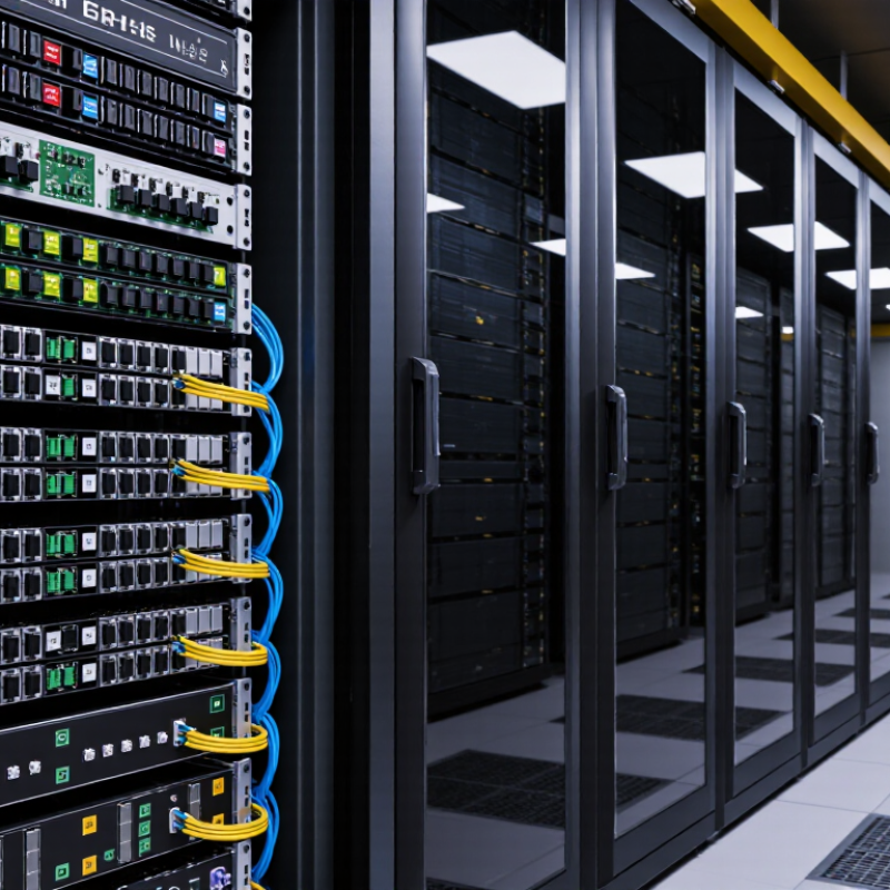
Single-mode transceivers send laser light through one narrow fiber core. This design reduces modal dispersion and preserves signal quality over long distances. Common types include SFP, SFP+, SFP28, QSFP28, QSFP-DD, and OSFP modules. Their speeds range from 1G to 800G, while transmission distances may reach 10, 40, 80, or more kilometers. Wavelengths near 1310 nm suit many metropolitan links. Wavelengths near 1550 nm often support longer spans and optical amplification. The IEEE 802.3 Ethernet standards define many of these reach and speed categories.
Demand for reliable optical links continues rising. The International Telecommunication Union’s Facts and Figures 2024 reports about 5.5 billion people used the Internet worldwide. That equals roughly 68% of the global population. More users mean heavier traffic between cities, cloud facilities, and network exchanges. Single-mode optics help operators connect these locations with fewer regeneration points. However, distance labels can mislead. Actual performance depends on fiber loss, connectors, dispersion, temperature, and receiver sensitivity. That is where specifications need careful checking.
Tips: Match the transceiver with the fiber type, connector, wavelength, and switch speed. Check the optical budget, not only the advertised distance. Keep a margin for aging and dirty connectors. Compatibility testing is still wise. Some “plug-and-play” choices are not truly simple. For global buyers, local certification and stable supply also deserve attention.
For global buyers in 2026, single-mode transceivers are no longer one uniform category. The practical choices span 10G LR, 25G LR, 100G LR4, 400G DR4, and emerging 800G designs.
IEEE 802.3 specifications typically define reaches from 500 meters to 10 kilometers for common single-mode links. That distance matters when a rack connects to a campus building. It also changes the fiber budget.
LightCounting’s 2025 Optical Transceiver Market Forecast identifies 400G and 800G modules as the fastest-growing speed classes. Omdia’s 2025 Optical Network Hardware Market Tracker also highlights higher-speed data-center optics as a major investment area.
For buyers, 100G LR4 remains practical for 10-kilometer links, especially where power and switch capacity are limited.
400G DR4 suits dense server fabrics, but it requires parallel single-mode fiber and careful polarity control.
800G can reduce port pressure. It can also expose cooling weaknesses.
Coherent single-mode pluggables deserve separate attention for metro and regional networks. They support longer reaches, flexible modulation, and stronger performance over difficult optical paths.
The Ethernet Alliance’s 2024 roadmap places 800G and 1.6T Ethernet among key future milestones, but deployment timing remains uneven.
My field experience suggests testing interoperability before volume orders. A datasheet rarely reveals every alarm or thermal issue.
That is the uncomfortable part. Reach, connector type, temperature rating, and DOM support should be checked against measured link loss, not marketing labels.
In 2026, single-mode transceivers differ mainly by wavelength, speed, reach, and connector design.
Wavelength shapes transmission distance and network planning. 1310 nm optics often suit shorter metropolitan links with moderate dispersion. 1550 nm options usually support longer spans and lower fiber attenuation. CWDM and DWDM types use multiple wavelengths, helping operators expand capacity without installing new fiber.
Speed must match the switch port and traffic pattern. Common choices include 1G, 10G, 25G, 100G, and higher-rate formats. A higher data rate may require better fiber quality, tighter loss control, and more careful thermal planning. Reach labels can be optimistic. Actual distance depends on splices, patch panels, bends, and optical power margins.
Distance changes everything.
Connector design affects installation speed and maintenance. Duplex LC connectors use two fibers for transmit and receive, while BiDi designs can reduce fiber usage through paired wavelengths. Higher-density systems may use multi-fiber connectors, but polarity errors can delay commissioning.
I have seen a clean rack become difficult to service because labels were too small. Small details matter.
Buyers should verify fiber type, connector polish, insertion loss, operating temperature, and digital diagnostics before approval. A specification sheet can still mislead when real cable conditions are ignored.
Matching transceiver specifications with network requirements starts with the fiber path, not the product label. Single mode modules usually serve long-distance links over OS2 fiber. Common options include 10G, 25G, 100G, and 400G variants. Select the data rate according to switch capacity and upgrade plans. A 100G module cannot solve a weak optical budget.
The ITU Facts and Figures 2024 report estimates that 5.5 billion people were online globally. Meanwhile, the June 2025 Mobility Report projects mobile data traffic to more than triple by 2030. These figures suggest stronger backbone demand, but capacity alone is not enough. Check wavelength, transmission distance, connector type, duplex design, and operating temperature. Then verify receiver sensitivity, transmit power, and maximum power consumption. Digital monitoring can reveal temperature, voltage, and optical drift before failures become visible. In real deployment work, compatibility is often the hardest variable. Standards compliance does not guarantee every platform will accept the same module. I have seen careful specifications fail during installation.
Tips: Measure the actual link loss. Leave an engineering margin. Confirm FEC requirements. Check DOM support. Test both ends before shipment. Avoid choosing 1550 nm simply because the distance looks impressive. 1310 nm may be more practical for a shorter metropolitan link. The calculation should reflect connectors, splices, patch panels, and future repairs. A small omission can become a costly truck roll.
2026 Top Single Mode Transceiver Types for Global Buyers
Before ordering, match the transceiver to the actual link, not just the advertised speed. Common options include 10G LR, 25G LR, 100G LR4, 400G DR4, and 400G FR4. Check reach, fiber count, connector type, wavelength, and duplex or parallel-fiber design. OS2 fiber is widely used for long-distance links, but existing cabling may still create limitations. IEEE 802.3 standards and SFF specifications provide useful compatibility references.
Demand continues to rise. Cisco’s Annual Internet Report estimated 5.3 billion internet users and 29.3 billion networked devices by 2023. That growth increases pressure on data-center and carrier infrastructure. LightCounting’s optical transceiver market research also identifies high-speed data-center optics as a major growth area through the decade. Buyers should verify power consumption, operating temperature, digital diagnostics, and host-platform coding before approving a purchase. A lower-cost module can become expensive after repeated field replacements.
Ask for test records, not promises. Confirm insertion loss, optical power, receiver sensitivity, and bit-error performance under realistic link conditions. Check whether the module supports monitoring through DOM and whether its firmware matches the intended equipment. In field audits, the fiber route is often misunderstood. A 10-kilometer label does not guarantee a stable 10-kilometer connection with dirty connectors or excessive loss. Procurement teams should review samples, lot consistency, warranty terms, and independent laboratory results. Specifications can look perfect on paper. Practice is less tidy.
| Transceiver Type | Nominal Data Rate | Typical Wavelength | Typical Single-Mode Reach | Fiber Requirement | Common Connector or Interface | Typical Operating Temperature | Common Applications | Key Checks Before Ordering |
|---|---|---|---|---|---|---|---|---|
| 1000BASE-LX / 1G LX | 1.25 Gb/s | 1310 nm | Up to 10 km | Duplex single-mode fiber; can also operate over selected multimode links with a mode-conditioning patch cable | Duplex LC, SFP form factor | Usually 0–70°C; industrial versions may support wider ranges | Enterprise access networks, campus links, storage and server connectivity | Confirm 1G port support, duplex or BiDi architecture, optical budget, connector polish, and switch compatibility. |
| 10GBASE-LR | 10.3125 Gb/s | 1310 nm | Up to 10 km | Duplex single-mode fiber | Duplex LC, SFP+ form factor | Usually 0–70°C; extended-temperature options are available | Data-center interconnection, metro access, enterprise backbone links | Verify host port coding, FEC expectations, maximum channel loss, fiber polarity, and whether the link requires DOM monitoring. |
| 10GBASE-ER | 10.3125 Gb/s | 1550 nm | Up to 40 km | Duplex single-mode fiber | Duplex LC, SFP+ form factor | Usually 0–70°C | Longer campus, metro and regional network links | Check receiver overload risk, total connector and splice loss, dispersion limits, and whether an attenuator is needed on short links. |
| 10GBASE-ZR | 10.3125 Gb/s | 1550 nm | Commonly up to 80 km; implementation-dependent | Duplex single-mode fiber | Duplex LC, SFP+ form factor | Usually 0–70°C | Extended-reach metro and regional optical transport | Confirm that both devices support the same extended-reach optical specification, and validate dispersion, power budget and receiver overload. |
| 25GBASE-LR | 25.78125 Gb/s | 1310 nm | Up to 10 km | Duplex single-mode fiber | Duplex LC, SFP28 form factor | Usually 0–70°C; industrial ranges depend on the module | Server-to-switch links, leaf-spine data-center networks, campus aggregation | Check switch lane rate, host FEC mode, breakout requirements, cable polarity, and the supported module temperature grade. |
| 40GBASE-LR4 | 41.25 Gb/s aggregate | Four lanes around 1310 nm | Up to 10 km | Duplex single-mode fiber using four wavelength lanes | Duplex LC, QSFP+ form factor | Usually 0–70°C | Data-center aggregation, campus core and short metro connections | Confirm QSFP+ port support, lane mapping, FEC behavior, optical power budget, and whether a 4×10G breakout is required. |
| 100GBASE-LR4 | 103.125 Gb/s aggregate | Four lanes around 1310 nm | Up to 10 km | Duplex single-mode fiber using four wavelength lanes | Duplex LC, QSFP28 form factor | Usually 0–70°C | Leaf-spine networks, data-center interconnects and campus backbone links | Verify QSFP28 support, FEC requirements, lane ordering, maximum insertion loss, connector cleanliness and interoperability testing. |
| 100GBASE-ER4 | 103.125 Gb/s aggregate | Four lanes around 1310 nm | Up to 40 km | Duplex single-mode fiber using four wavelength lanes | Duplex LC, QSFP28 form factor | Usually 0–70°C | Metro data-center interconnects and regional aggregation | Validate optical budget, dispersion, receiver overload, FEC compatibility, connector loss and the actual distance of the installed route. |
| 100GBASE-DR | 103.125 Gb/s aggregate | 1310 nm; four 25G electrical and optical lanes | Up to 500 m | Duplex single-mode fiber | Duplex or dual-pair MPO-12, QSFP28 or QSFP56 depending on implementation | Usually 0–70°C | High-density data-center leaf-spine and server-area interconnection | Check the exact connector arrangement, parallel-fiber polarity, breakout cable type, FEC mode and switch electrical interface. |
| 400GBASE-FR4 | 425 Gb/s aggregate | Four lanes around 1310 nm | Up to 2 km | Duplex single-mode fiber using four wavelength lanes | Duplex LC, QSFP-DD or OSFP form factor | Usually 0–70°C; platform limits must be checked | High-capacity data-center interconnects and short campus backbone links | Confirm module form factor, host FEC, cage and power limits, optical budget, LC polarity and thermal clearance. |
| 400GBASE-LR4 | 425 Gb/s aggregate | Four lanes around 1310 nm | Up to 10 km | Duplex single-mode fiber using four wavelength lanes | Duplex LC, QSFP-DD or OSFP form factor | Usually 0–70°C; platform limits must be checked | Data-center interconnects, metro aggregation and high-capacity backbone links | Check host electrical lane configuration, FEC, power consumption, port density, optical loss budget and equipment interoperability. |
| 400GBASE-DR4 | 425 Gb/s aggregate | 1310 nm; four parallel optical lanes | Up to 500 m | Parallel single-mode fiber | One MPO-12 or equivalent parallel-fiber interface, QSFP-DD or OSFP form factor | Usually 0–70°C; platform limits must be checked | High-density data-center spine, leaf and GPU-cluster interconnection | Confirm MPO polarity, lane mapping, fiber count, breakout design, FEC, module power and the required transceiver cage type. |
| BiDi Single-Mode SFP/SFP+ | 1G or 10G, depending on model | Paired wavelengths, commonly 1270/1330 nm or 1310/1490 nm | Commonly 10–40 km | One single-mode fiber strand | Simplex LC, SFP or SFP+ form factor | Usually 0–70°C | Fiber-constrained access networks, surveillance uplinks and building-to-building links | Order matched wavelength pairs, confirm A-side/B-side orientation, verify optical budget and ensure both ends use compatible data rates. |
| CWDM Single-Mode SFP/SFP+ | 1G or 10G, depending on model | Typical CWDM channels from 1271 nm to 1611 nm, spaced at 20 nm | Commonly 10–80 km, depending on wavelength and optical budget | Duplex single-mode fiber or a passive CWDM multiplexing system | Duplex LC, SFP or SFP+ form factor | Usually 0–70°C | Metro aggregation, campus wavelength multiplexing and fiber-capacity expansion | Confirm channel plan, mux/demux loss, wavelength pairing, fiber attenuation, optical power budget and connector type. |
| DWDM Tunable or Fixed-Wavelength Module | 10G, 25G, 100G or higher, depending on implementation | ITU-T grid wavelengths, commonly in the C-band near 1550 nm | Typically 40–80 km without amplification; longer routes require engineered optical transport | Duplex single-mode fiber with wavelength-management equipment | LC, duplex LC, or platform-specific high-speed interface | Usually 0–70°C; coherent modules may have stricter power and thermal limits | Metro and regional transport, data-center interconnects and wavelength-routed networks | Confirm channel spacing, tunability, line-system compatibility, launch power, dispersion compensation, FEC and optical amplification requirements. |
It sends laser light through one narrow fiber core. This reduces modal dispersion and preserves signal quality over long distances. Simple idea. Common speeds range from 1G to 800G.
Typical reaches include 10, 40, and 80 kilometers. Some modules support longer spans. The label is not a guarantee. Fiber loss, connectors, bends, temperature, and receiver sensitivity can reduce the real distance.
Wavelengths near 1310 nanometers often suit metropolitan connections. Wavelengths near 1550 nanometers commonly support longer spans. They may also work with optical amplification. Planning still requires measured link loss.
Common choices include 10G, 25G, 100G, 400G, and emerging 800G modules. Higher speeds can reduce port pressure. They may also increase cooling demands. More capacity is not always easier.
Match the module with fiber type, connector, wavelength, and switch speed. Check the optical budget carefully. Leave margin for aging and dirty connectors. Confirm temperature ratings and digital diagnostics.
Duplex designs use separate fibers for sending and receiving signals. BiDi designs use paired wavelengths over one fiber. This can reduce fiber use. Paired modules must match correctly.
High-speed modules may need parallel single-mode fibers and accurate polarity control. Cooling and power conditions also matter. A clean datasheet may hide thermal or alarm problems. Test interoperability before large orders.
Duplex LC connectors are familiar and relatively simple to service. Multi-fiber connectors support dense installations but increase polarity risks. Small labels can create large maintenance problems. Details matter.
No. Real performance depends on splices, patch panels, bends, insertion loss, and power margins. A short test link can look perfect. Longer field conditions may expose weaknesses. That deserves honest review.
In 2026, a single mode transceiver remains a key component for reliable, long-distance fiber-optic communication. Designed to transmit signals through narrow-core single-mode fiber, it supports links that reach far beyond the limits of standard short-range solutions. Global buyers can choose from various types based on speed, transmission distance, operating wavelength, form factor, and application needs, including options for data centers, telecom networks, metropolitan connections, and enterprise backbones.
Selecting the right transceiver requires careful comparison of wavelength, data rate, reach, connector design, fiber compatibility, and network architecture. Buyers should confirm whether the module matches their switches, routers, and optical infrastructure, while also checking interoperability, operating temperature, power consumption, compliance documentation, availability, warranty terms, and supplier support. A clear understanding of present and future bandwidth requirements can help prevent compatibility issues, reduce replacement costs, and ensure stable performance throughout the network’s service life.
